L350/L300/L355/L210/L110 Series Revision B
Disassembly/Reassembly Detailed Disassembly/Reassembly Procedure for each Part/Unit 42
Confidential
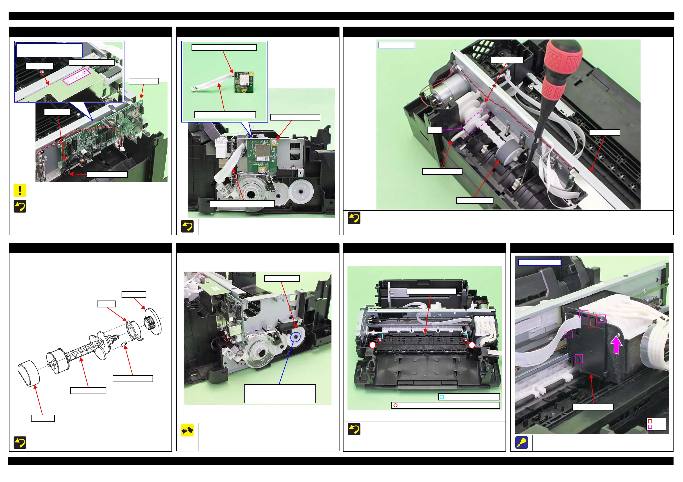
Main Board
Do not damage or contaminate the MAC Address Label.
(L355 Series only)
Install the Main Board with the PE Sensor Lever to the rear.
After installing the Main Board, make sure the lever part of the
PE Sensor Lever is aligned with the slit of the PE Sensor.
Attach the MAC Address Label to the Shield Plate on the
position shown above.
MAC Address Label
Shield Plate
Position of MAC Address Label
(L355 Series only)
PE Sensor Lever
Main Board
PE Sensor
Wireless LAN Module (L355 Series)
Attach two pieces of acetate tape on the Wireless LAN Module
cable to cover the cable to protect it as shown above.
Wireless LAN Module
Wireless LAN Module Cable
Wireless LAN Module Cable
Cover with acetate tape (x2).
LD Roller Assy (1)
Install the LD Roller Assy with the following condition in order to avoid the Change Lever and Paper Back Lever.
Using a screw driver or the like, hold the Paper Back Lever to the rear as shown above not to let it touch the LD Roller Assy.
Push the Change Lever to the front to keep it in the hole of the Main Frame.
LD Roller Assy
Paper Back Lever
Change Lever
Cam
Main Frame
Rear of printer
LD Roller Assy (2)
If each part shown above comes off when removing the LD Roller
Assy, attach them back in place as shown in the figure above.
LD Roller
LD Roller Shaft
Extension Spring
Clutch
Spur gear
EJ Roller Gear
The rib on the contact point of the EJ Roller Gear with the EJ
Roller is deformed when removing the EJ Roller Gear. Therefore,
make sure to replace it with a new one when removing it in order to
maintain the paper feed accuracy.
EJ Roller Gear
Can not be reused because the rib
of the EJ Roller Gear is deformed
once removed from the EJ Roller.
Paper Guide Front Unit
When installing the Paper Guide Front Unit, align the
positioning holes (x2) of the Paper Guide Front Unit with the
dowels (x2) of the Frame Base.
Tighten the screws in the order indicated in the figure above.
1 2
Paper Guide Front Unit
Dowel and positioning hole
C.B.P-TITE SCREW 3x10 F/ZN-3C (6 ± 1 kgf·cm)
FFC Cover Outer
Slide and remove the FFC Cover Outer in the direction of the arrow
while releasing the hook.
Hook
Rib
FFC Cover Outer
Left side of CR Unit
 Loading...