L
leahcooperJul 27, 2025
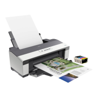
What to do if my Epson Stylus Office T1110 has a paper jam?
- SScott HernandezJul 27, 2025
If your Epson Printer indicates a paper jam, press the Paper button on the printer or click the [Eject] button on the screen, if it appears. Then, manually remove any remaining jammed paper.