Home
Epson
Printer
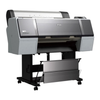
Stylus Pro 7900
Repair Guide
Page 136 (Ink Bay Installation (Right))
Epson Stylus Pro 7900 - Ink Bay Installation (Right)
469 pages
Manual
To Next Page
To Next Page
To Previous Page
To Previous Page
Loading...
Pro 7900 and 9900 Fiel
d Repair Guide
10/6/10
Ink Bay Installati
on (Right)
Printer Component,
Software Item,
LCD Display
,
Printer Button
Page 136.
Ink Bay Inst
allation (Right)
1.
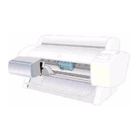
Install the
Right Ink Bay
.
Place the
Right Ink Bay
in position.
135
137
Table of Contents
Main Page
Table of Contents
1
Control Panel Map
7
Printers LCD Display
8
Self Testing
8
User Menu
9
Printer Setup
9
Maintenance
9
Printer Status
9
Paper Setup
10
Head Alignment
10
Network Setup
10
Options Setup
10
NVRAM Data (Parameter) Backup Mode
11
NVRAM Data (Parameter) Restore Mode
11
F/W Download Mode
11
Maintenance Mode 1
11
Component Replacement
16
Board (AID) Removal
17
Board Carriage Removal
19
Board (Main) Removal
23
Main Board Removal (Overview)
23
Main Board Removal (Detail)
23
Board (Main) Installation
26
Main Board Installation (Overview)
26
Main Board Installation (Detail)
26
Board (Power Supply) Removal
33
Board (Sub B) Removal
35
Board (Sub C) Removal
37
Cleaning Unit Removal
39
Cleaning Unit Installation
46
Cover (Cutter Assembly) Removal
53
Cover (Left Side) Removal
56
Cover (Rear) Removal
64
Remove the Rear Cover
65
Cover (Rewind Assembly) Removal
66
Cover (Right Side) Removal
69
Remove the Control Panel
76
Cover (Top) Removal
78
Cutter Assembly Removal
82
Damper (Selector) Assembly Removal
91
Ink Bay (Left) Removal
104
Ink Bay Installation (Left)
115
Ink Bay (Right) Removal
126
Ink Bay Installation (Right)
136
Pressure Pump Assembly Removal
146
Print Head Removal
148
Print Head Removal Overview
148
Print Head Removal Detail
148
Print Head Installation
159
Sensor (Carriage Encoder) Removal
170
Sensor (Edge Detector) Removal
173
Sensor (Ink Mark) Removal
178
Sensor (Platen Gap) Removal
183
Wiper Blade Assembly Removal
188
Troubleshooting
191
Printer Error Codes (Maintenance)
192
Printer Error Codes (Service)
193
11Xx Series Carriage Error Codes
193
13Xx Ink Cover Error
198
14Xx Ink System/Cap Assembly Errors
198
Printer Options Error Codes
213
1537 Error
218
AID Issue Troubleshooting
219
Borderless Printing Errors
221
Color Shift
222
Grainy or Ghosting
223
Horizontal Banding
224
Feed Related
224
Ink Cartridge Error: Replace Ink Cartridge
226
Missing Nozzle Diagnosis
231
Definitions
231
Color Pair Missing (Completely, or Almost Completely)
232
All Channels Missing
232
Some Nozzles Missing
232
Some Nozzles Drop out While Printing
233
PCU (Plate Curing Unit) Troubleshooting
235
Required Equipment
235
Test Procedure
235
Random Nozzle Firing
240
Head Cable
240
Print Head or Main Board
240
Power Supply
240
Scratch
241
Smear
242
Smudge
243
Dirty Roller
243
Print Head
243
Spectroproofer Troubleshooting
244
Install and Connect the Spectroproofer
244
Correct with the Pins in These Holes
247
Incorrect with the Pins Not in These Holes
247
Stuck in Cut Sheet Mode
250
Vertical Banding
251
Saturation Related Vertical Banding
251
Alignment Related Vertical Banding
251
Carriage Motor Related Vertical Banding
251
Adjustments
252
AID Check Test
253
Check Network Communication
254
Clear Counter [When Replacing AID]
257
Clear Counter [When Replacing Cartridge Holder Ink Pad]
260
Clear Counter [When Replacing CR Motor]
263
Clear Counter [When Replacing Ink Holder]
266
Clear Counter [When Replacing Ink Tube]
269
Clear Counter [When Replacing PF Motor]
272
Clear Counter [When Replacing Pressurizing Motor]
275
Clear Counter [When Replacing Printhead]
278
Clear Counter [When Replacing Pump Motor
281
Clear Counter [When Replacing Wiper]
284
Cleaning PG Adjustment
287
CR Head Slant Adjustment
291
CTP Plate Guide Alignment
294
Feed Adj(Ustment)
300
Head Rank Input Adjustment
302
Initial Ink Charge Flag
306
Ink Holder Assy Adjustment
309
Ink Mark Sensor Position Adjustment
312
Input CR Motor Current Adjustment
316
Input MAC Address Adjustment
319
Input PF Motor Current Adjustment
325
Input Serial Number Adjustment
328
Nv-Ram Backup Utility
331
Paper Thickness Sensor Adjustment
332
PF Slant Adjustment
335
About the 7900 and 9900 PF Slant Adjustment
335
Required Files
335
Rear AD Sensor Adjustment
343
RTC & USB ID Adjustment
344
Sensor (Carriage Encoder) Adjustment
347
Setting Destination Adjustment
349
TBS Pos Adjustment
352
Component Pictures
354
Board (AID) Picture
355
Located above the Cap Assembly
355
Board Carriage (CA11) Picture
356
Located on the Carriage Mechanism
356
Board (Sub-B) Picture
357
Located on the Right Side Frame
357
Board (Sub-C) Picture
358
Located on the Left Side Frame
358
Board (Main) Picture
359
Board (Power Supply) Picture
360
Carriage Assembly Pictures
361
Left Side View
361
Right Side View
362
Top View
363
Bottom View
364
Carriage Motor Pictures
365
Cleaning Unit Pictures
366
Wiper Blade and Flushing Box
367
Rear View
368
Pump Assembly
369
Control Panel Pictures
370
Cutter Assembly Pictures
371
Damper (Selector) Assembly Pictures
372
Pressure Pump Assembly Pictures
374
Print Head Pictures
378
7900 And 9900 Head Rank Sticker
379
Sensor (Carriage Encoder) Pictures
381
Sensor (Edge Detector) Picture
382
Sensor (Ink Mark) Picture
383
Sensor (Platen Gap) Picture
384
Wiper Blade Assembly Picture
385
Reference
386
Accessories List
387
Carriage Release (Auto)
388
Auto Carriage Release Method
388
Carriage Release (Manual)
389
Manual Carriage Release Method
389
Manual Carriage Lock
391
Cleaning Cycles (Types and Uses)
393
About All Cleaning Cycles
393
Normal Cleaning
393
Color Pair Cleaning
394
Power Cleaning
394
SS Cleaning
394
Color Order
395
Color Order for Installed Cartridges
395
User Nozzle Check Color Order
395
Color Pairs on the Print Head (Listed Left to Right)
396
Connectors / Wiring
397
Main Board Connectors
397
C594 Sub-B Board
398
C594 Sub-C Board
399
Carriage Board (CA11 Sub Board)
400
Power Supply
401
Consumable/Service Parts List
402
Cover Sensor (Front) Bypass Procedure
404
Cover Sensor (Ink) Bypass Procedure
405
CTP(7900) (Computer to Plate) Explanation
406
What Is the 7900CTP
406
Items Included with the 7900CTP
406
Service Implications
406
Optional Plate Guide Picture
409
Firmware History (Ethernet)
410
Firmware History (Printer) (7900)
411
Stylus Pro 7900 Firmware Ver. Hn028A4.Upg
412
Stylus Pro 7900 Firmware Ver. Hn0239A.upg
412
Stylus Pro 7900 Firmware Ver. Hn02995.Upg
413
Stylus Pro 7900 Firmware Ver. Hn02793.Upg
413
Stylus Pro 7900 Firmware Ver. Hn01692.Upg
413
Firmware History (Printer) (9900)
415
Stylus Pro 9900 Current Firmware Ver. Hw003A9.Upg
415
Stylus Pro 9900 Firmware Ver. Hw028A4.Upg
416
Stylus Pro 9900 Firmware Ver. Hw0239C.upg
417
Stylus Pro 9900 Firmware Ver. Hw0239A.upg
417
Stylus Pro 9900 Firmware Ver. Hw01699.Upg
417
Stylus Pro 9900 Firmware Ver. Hw02995.Upg
418
Stylus Pro 9900 Firmware Ver. Hw02793.Upg
418
Stylus Pro 9900 Firmware Ver. Hw01692.Upg
418
Stylus Pro 9900 Firmware Ver. Hw0148A.upg
418
Firmware Update Procedure Using Fwupdate.exe
419
Ink Draining Procedure
420
Media Feed Step (About)
422
Glossary
423
Prime, on or off
429
Revision History
430
Sensors, Motors, Solenoids, and Fans
436
Home Position Sensors
436
Status Sensors
436
Service Procedure (Recommended)
439
Service Tools
441
Stress Test (Test Image)
442
Utilities
443
Epson Net Config 2.2B
444
Main Screen
445
Fwupdate.exe
449
At Main Board Exchange
453
Nv-Ram Backup Utility
453
Nvram Backup
457
NVRAM Restore
461
Remote Panel 2 (Epson LFP)
464
Servprog.exe
466
Other manuals for Epson Stylus Pro 7900
User Guide
238 pages
Guide
208 pages
Ordering Guide
2 pages
Unpacking And Setup Guide
30 pages
User Report
10 pages
Product Information
78 pages
Brochure & Specs
8 pages
Related product manuals
Epson Stylus Pro 7800
393 pages
Epson Stylus Pro 7500
274 pages
Epson Stylus Pro 7600
5 pages
Epson Stylus Pro 7880
218 pages
Epson Stylus Pro 7890
190 pages
Epson Stylus Pro 7000
12 pages
Epson Stylus Pro 7710
519 pages
Epson Stylus Pro 7400
428 pages
Epson Stylus Pro 7700
519 pages
Epson Stylus Color 740
24 pages
Epson Stylus Photo 750
166 pages
Epson Stylus Artisan 730
104 pages