Epson WF-7620 / WF-7610 / WF-7110 Series Revision B
Disassembly/Reassembly Detailed Disassembly/Reassembly Procedure for each Part/Unit 42
Confidential
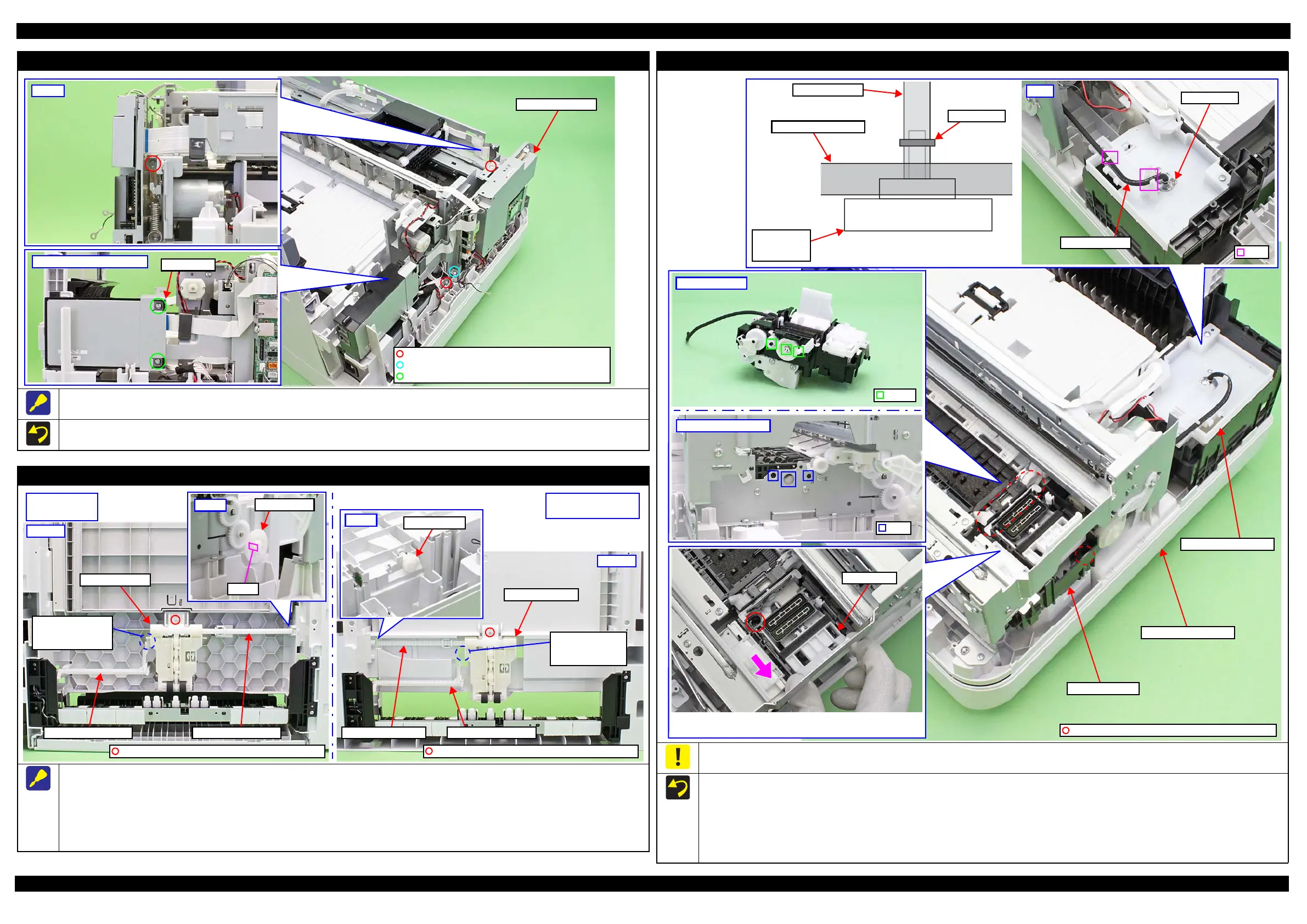
Main Board Unit
The screws that secure the Main Board Unit are shown above.
Tighten the screws in the order indicated in the figure above.
Main Board Unit
C.B.S-TITE SCREW 3x6 F/ZN-3C (8±1 kgf·cm)
FAX Unit
WF-7620/7610 Series only
C.B.P-TITE SCREW 3x10 F/ZN-3C (6±1 kgf·cm)
C.B.P-TITE SCREW 3x10 F/ZN-3C (8±1 kgf·cm)
Ink system Assy
When connecting the Waste Ink Tube to the Maintenance Box Waste Ink Joint, connect it until the edge of the tube touches the root on the joint to
prevent waste ink from leaking.
When installing the Ink System Assy, follow the procedure below.
1. Route the Waste Ink Tube under the Main Frame.
2. Aligning the dowels (x3) on the Ink System Assy with the holes (x3) on the Frame Base 1st Assy.
3. Secure the Ink System Assy with screws (x2).
4. Connect the joint section of the Waste Ink Tube with the joint of the Maintenance Box Waste Ink Joint, then secure them with the Tube Clamp.
5. Route the Waste Ink Tube through the ribs (x2) on the Frame Base.
Rear
Tube Clamp
Rib
Waste Ink Tube
Frame Base 1st Assy
Ink system Assy
Waste Ink Tray Cover
Waste Ink Tube
Maintenance
Box Waste
Ink Joint
Tube Clamp
C.B.P-TITE SCREW 3x10 F/ZN-3C (6±1 kgf·cm)
Slide the Cap Slider in the direction of the arrow, then secure the
Ink System with a screw.
Waste Ink Tray Cover
Pickup Assy 1st/2nd
When removing the Pickup Assy 1st / 2nd, follow the procedure below.
1. Release the Pickup Assy 1st / 2nd from the Pickup Escape Lever.
2. Remove the screws (x1 each) that secure the Pickup Assy 1st / 2nd.
3. Pickup Assy 1st: Release the hook of the Spur Gear 32 and remove the Spur Gear 32 from the Pickup Driven Shaft, and then pull out the
shaft from the hole of the Frame Base Assy, and remove the Pickup Assy 1st.
4. Pickup Assy 2nd: Remove the Pickup Driven Shaft from the Spur Gear 16, and remove the Pickup Assy 2nd from the 2nd Bin Base Assy.
Pickup Driven ShaftPickup Escape Lever
Pickup Assy 1st
The location where
the Pickup Escape
Lever interferes.
Bottom
Pickup Assy 1st
(Common to all)
C.B.P-TITE SCREW 3x10 F/ZN-3C (6±1 kgf·cm)
C.B.P-TITE SCREW 3x10 F/ZN-3C (6±1 kgf·cm)
Pickup Escape LeverPickup Driven Shaft
The location where
the Pickup Escape
Lever interferes.
Pickup Assy 2nd
(WF-7620/7110 Series)
Pickup Assy 2nd
Bottom
 Loading...