Epson WF-7620 / WF-7610 / WF-7110 Series Revision B
Disassembly/Reassembly Detailed Disassembly/Reassembly Procedure for each Part/Unit 43
Confidential
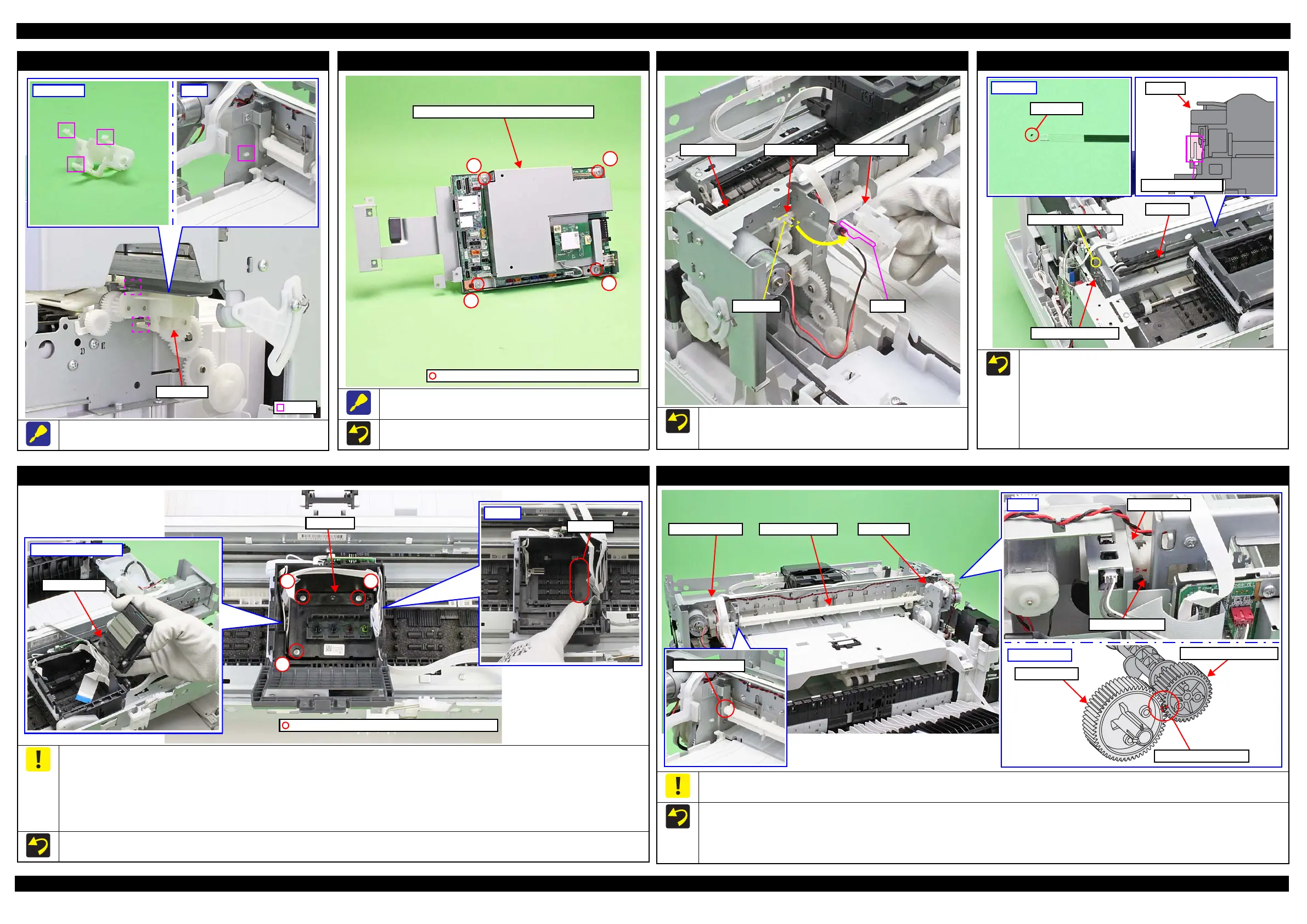
Gear Cover
Release the hooks (x3) shown above before removal.
Shield Plate Upper (w/Wireless LAN Module)
The screws (x4) that secure the Shield Plate Upper (w/ Wireless
LAN Module) are shown above.
Tighten the screws in the order indicated in the figure above.
Shield Plate Upper (w/Wireless LAN Module)
C.B.S-TITE SCREW 3x6 F/ZN-3C (8±1 kgf·cm)
1
2
3
4
Holder Cam Assy
When installing the Holder Cam Assy to the Main Frame, insert the
protrusion of the D/E Lever into the groove of the Holder Cam
Assy.
Holder Cam AssyD/E Lever
Protrusion Groove
Main frame
CR Scale
Install the CR Scale with the black mark section on the top left.
Make sure to put the CR Scale through the slit of the CR Encoder.
When attaching the Torsion Spring 7.13, follow the procedure below.
1. Attach the Torsion Spring 7.13 to the CR Guide Plate, and hook
the shorter leg of the Torsion Spring 7.13 on the CR Scale.
2. Hook the longer leg of the Torsion Spring 7.13 to the cutout of
the Main Frame to complete the Torsion Spring 7.13 attachment.
CR Unit
Slit of CR Encoder
CR Scale
Torsion Spring 7.13
Cutout of Main Frame
Printhead
Waste ink easily collects around the waste ink pad on the Printhead after printing and around the section A of the CR Unit shown above. When
removing the Printhead, take care not to let the terminal of the disconnected FFC touch the area around the section A. When reassembling the
Printhead, be careful not to let the terminal of the disconnected FFC touch the area around the waste ink pad. Take care in the same way when
replacing the Printer Mechanism and transferring the Printhead. If you connect the FFC to the connector with waste ink attached on the terminal,
the circuit board may be short-circuited. Therefore, if any waste ink is attached on the terminal, make sure to wipe the ink off completely with a
dry cloth or the like.
After removing the Printhead, place the Printhead with the nozzle surface up so as to prevent the remaining ink in the Printhead from flowing out.
Tighten the screws in the order indicated in the figure above.
Bottom of Printhead
Waste ink pad
1
C.B.P-TITE SCREW 2.5x8 F/ZN-3C (4±1 kgf·cm)
2
3
APG Driven Shaft
Because the disassembly/reassembly of the APG Driven Shaft should be done in a very narrow space, take care not to damage the gears of the APG
Driven Shaft or APG Unit by hitting them with the edges of the frame or the like.
Install the APG Driven Shaft as follows.
1. Insert the gear of the APG Driven Shaft into the space between the APG Unit and Main Frame Unit.
2. Insert the protrusion of the APG Driven Shaft into the hole on the Main Frame Unit.
3. Align the phases of the gear of the APG Driven Shaft and the Spur Gear 32.4 on the APG Unit, then attach the APG Driven Shaft.
Right
APG Driven Shaft
Spur gear 32.4
Aligning phases
Gear of APG Driven Shaft
Spur gear 32.4
Align the triangle marks.
 Loading...