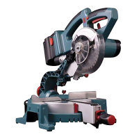
6. HOLD DOWN CLAMP
1. Hold down clamps can be tted on either side
of the saw and are fully adjustable to suit the size
of the workpiece (see g 8). The clamp will t into
either of the posts integrated into the machine
fence.
2. Do not operate the saw without clamping the
workpiece.
3. Make sure that the hold down clamp securing
screws are tightened.
Warning: Always check clamp position does not
interfere with any saw operation. Before switching
on, lower the saw head to ensure the clamp
clears the guard and saw head assembly.
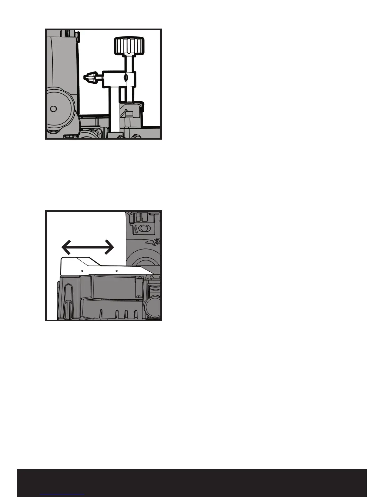
7. FENCE
The width of the fence ‘mouth’ can be altered
by adjusting the LH side of the fence. This
may be necessary to provide clearance for the
blade when extreme mitre and bevel angles are
selected. (Fig 9)
1. Ensure that the battery is removed from the
machine.
2. Loosen the two countersunk headed screws
with the hex key provided.
3. Slide the adjustable fence front plate to the
desired position.
4. Check that the blade does not foul the fence by
conducting a ‘dry run’ with the cutting head set to
the required bevel and mitre angle.
5. When satised that the blades path is
unobstructed tighten the two screws and replace
the battery.
Fig 8
Fig 9
ERBAUER 24V 165MM SINGLE BEVEL MITRE SAW