27 / 62
8 • Adjustment
80116-276_V24169
2022-01
Test setup
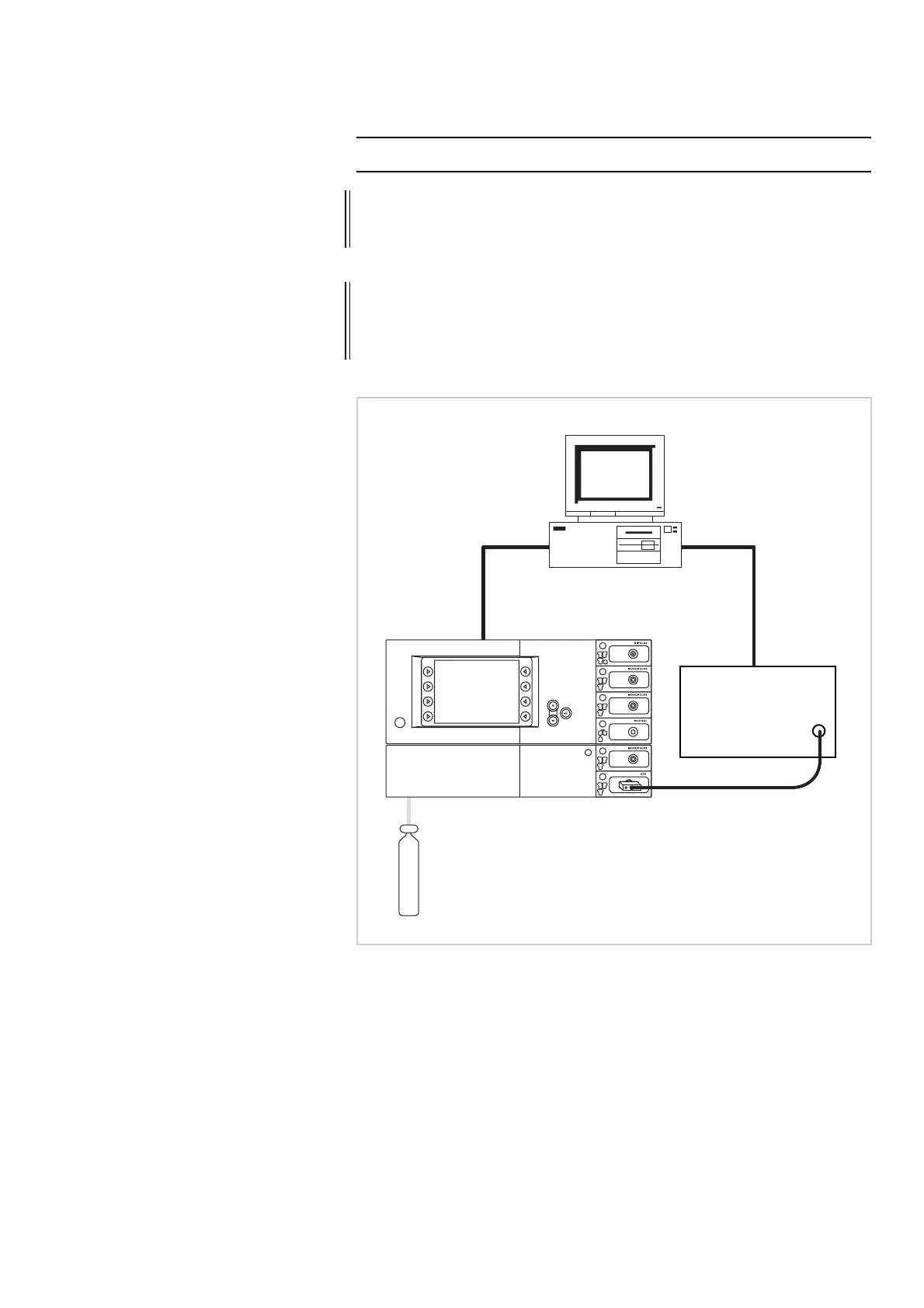
Fig. 8-1
• The test setup is designed as shown in the illustration above. In this
case a unit combination comprised of APC 2 + VIO D serves as an
example.
• On the PC the "VIO APC Adjustment Tool" software is installed.
• With FiAPC socket (see picture above): The FiAPC test adapter is con-
nected to the FiAPC socket. The gas outlet of the test adapter is con-
nected to the ITP flowmeter via the test hose.
• With APC socket (not illustrated): The gas outlet of the APC socket is
connected to the ITP flowmeter via the test hose.
IMPORTANT! During adjustment of the APC 2 the APC 2 and the VIO electrosurgical
unit must not under any circumstances be connected with one another
via ECB.
IMPORTANT! Erbe recommends using an argon pressure cylinder to supply the argon
gas to adjust the APC
2. In addition, original Erbe pressure reducers for
APC
2 should be used. For article numbers see chapter "Testing and
measuring equipment".
,73Omega
IORZPHWHU
30100-528
'HVNWRSPC
(&%FRQQHFWLRQ
,732PHJD
GDWDFDEOH
APCWHVWKRVH
20100-165
Argon