10 • Maintenance and servicing
46 / 62
80116-276_V24169
2022-01
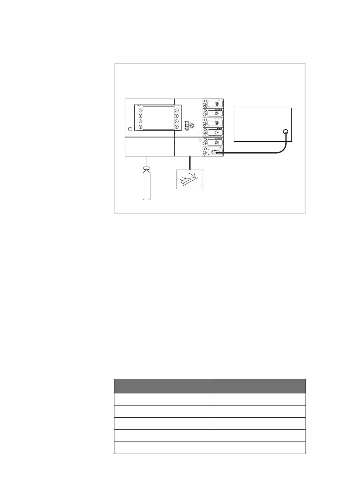
Test setup
Fig. 10-1
• The test specimen is connected to the power supply via a VIO HF surgi-
cal unit. A VIO D unit serves as an example in this case.
• The argon gas bottle is connected to the test specimen.
• The dual-pedal footswitch with ReMode is connected.
• With FiAPC socket (see picture above): The FiAPC test adapter is con-
nected to the FiAPC socket. The gas outlet of the test adapter is con-
nected to the ITP flowmeter via the test hose.
• With APC socket (not illustrated): The gas outlet of the APC socket is
connected to the ITP flowmeter via the test hose. The VIO APC hand-
piece is electrically connected to the APC socket.
Test procedure
1. On the VIO HF surgical unit set the first flow setpoint of 0.2 l/min.
2. Activate test specimen via the footwitch.
3. Document the measured value.
4. Repeat the test with all the flow setpoints on the table below. All the
measured values must be within the specified tolerance ranges.
Flow setpoint Tolerance range
0.2 l/min 0.16 – 0.24 l/min
0.5 l/min 0.40 – 0.60 l/min
1.0 l/min 0.80 – 1.20 l/min
2.0 l/min 1.60 – 2.40 l/min
5.0 l/min 4.00 – 6.00 l/min
ITPOmega
IORZPHWHU
30100-528
Argon