EASY-ROTOR-CONTROL M V2.2 Instructions
___________________________________________________________________________
© Ing.-Büro E. Alba de Schmidt web : www.schmidt-alba.de
Tannenstr. 16 Page 20 of 44 email : erc@schmidt-alba.de
86836 Untermeitingen / Germany
This document is for the user only. Any publishing (printed or in electronic form) is not allowed.
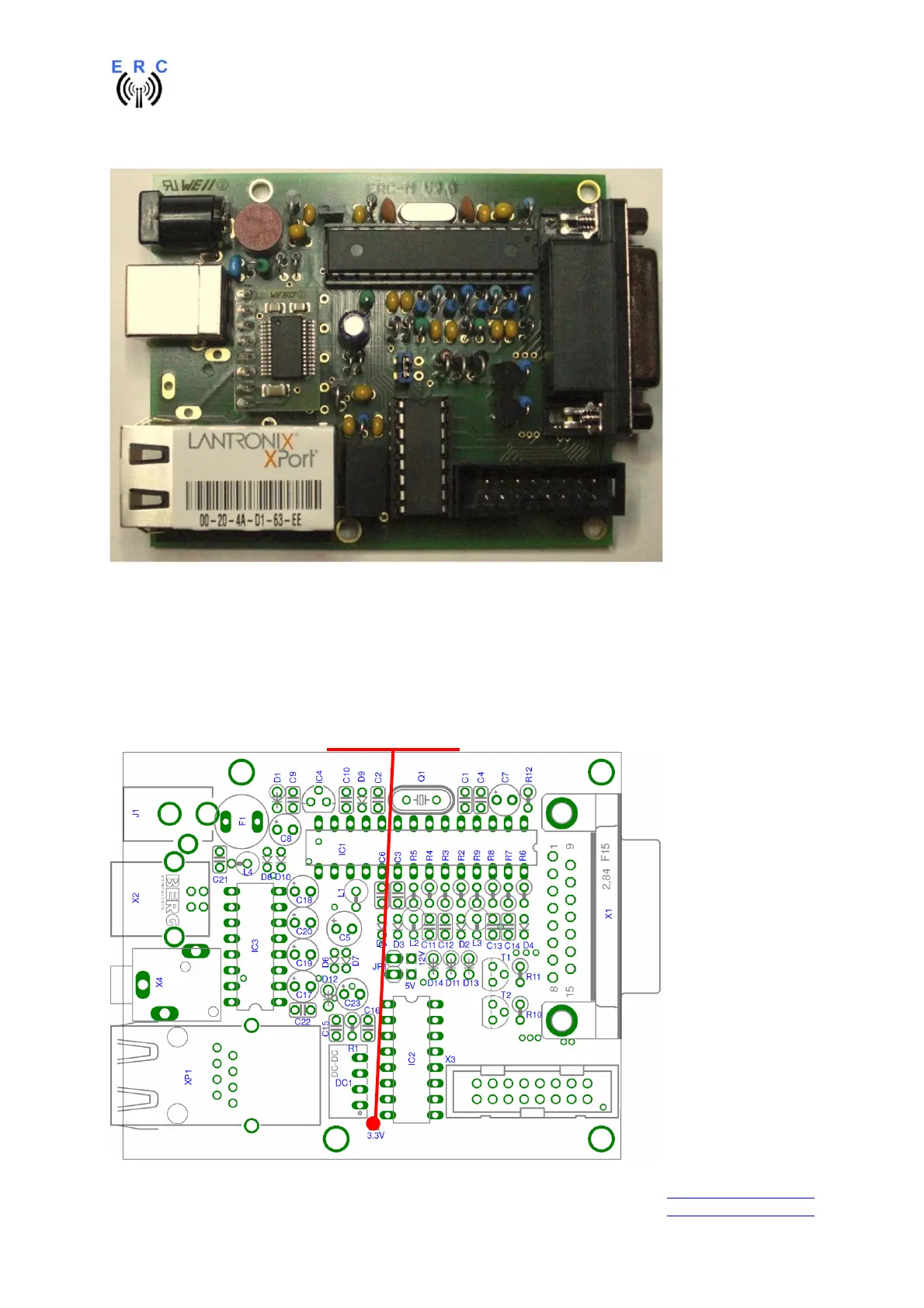
This is how it should look like:
3.4 Check of the DC/DC-converter
After checking all assembled components for identity, polarization and solder-bridges, connect 10 to
15VDC to connector J1 as already performed in chapter 1.3.
After connecting DC correctly, you should measure +3.3VDC +/-0.4V at the testpoint shown against
GND.
Testpoint : +3.3V
GND