8
GBGB
GBGB
GB
PRELIMINARY HARDWAREPRELIMINARY HARDWARE
PRELIMINARY HARDWAREPRELIMINARY HARDWARE
PRELIMINARY HARDWARE
SETTINGSSETTINGS
SETTINGSSETTINGS
SETTINGS
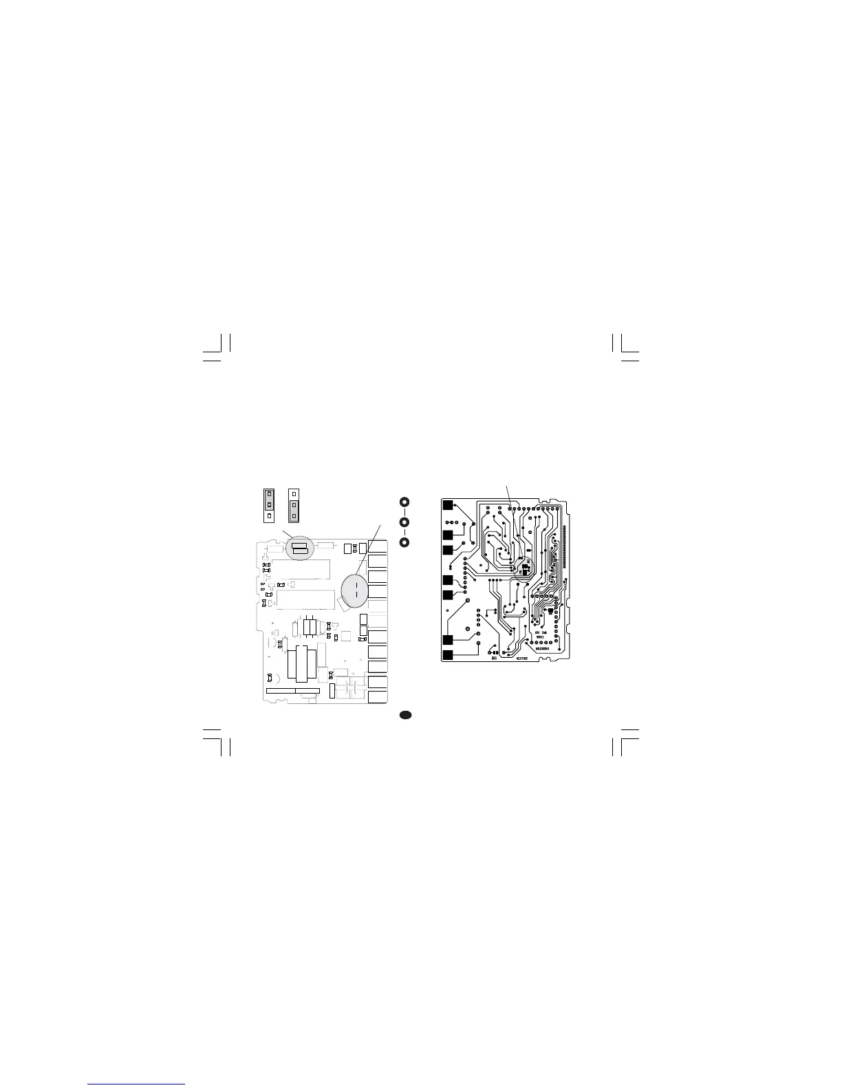
1) Remove the instrument from its case.
2) For out 1 and 2 it is possible to select the
desired output type by setting the J304 and J305
jumpers.
J304 (AL1, Cool.) 1-2 = SSR 2-3 = Relay
J305 (OUT 1) 1-2 = SSR 2-3 = Relay
3) For out 2 it is possible to select the used relay
contact (NO or NC) by setting J303 jumper.
J303 (AL1, Cool.) 1-2 = Out NO 2-3 = Out NC
Note Note
Note Note
Note : J303 is a soldering jumper and it is located
on the soldering side of the card.
Fig 11
OPEN INPUT CIRCUITOPEN INPUT CIRCUIT
OPEN INPUT CIRCUITOPEN INPUT CIRCUIT
OPEN INPUT CIRCUIT
These device are capable to detect leads break
for TC and RTD inputs. For RTD input it shows
this status as an overrange condition.
For thermocouple input only, it is possible, to
select the overrange indication (standard) by
closing CH2 and opening SH2 or underrange
indication by closing SH2 and opening CH2.
SH2 and CH2 are located on the soldering side of
the CPU card (see fig.12).
Fig. 12
1
1
1
23
4
+
-
+
B
C
E
I
1
3
4
7
1
1
XY00
I
1
2
3
12
3
45
12
345
J301
J302
L305
R301
R303
D
3
0
5
C308
C306
C307
R305
C312
C310
D307
R308
C309
PZ12
PZ13
PZ14
PZ15
PZ16
PZ19
PZ20
PZ21
PZ22
R307
R306
Q302
U302
TR301
J304
J305
Y301
D306
D308
D304
U301
PZ18
PZ17
C301
C
3
0
4
J303
C303
C311
C302
C305
C314
C313
L304
L301
L303
L302
R309
R310
R312
R314
R311
R302
R304
R313
Q303
Q305
D302
Q301
Q304
D301
D310
K302
K301
J 303
1
1
3
J304 J305
CH2
SH2