19
GBGB
GBGB
GB
ERROR MESSAGESERROR MESSAGES
ERROR MESSAGESERROR MESSAGES
ERROR MESSAGES
OVERRANGE, UNDERRANGE AND BURNOUTOVERRANGE, UNDERRANGE AND BURNOUT
OVERRANGE, UNDERRANGE AND BURNOUTOVERRANGE, UNDERRANGE AND BURNOUT
OVERRANGE, UNDERRANGE AND BURNOUT
INDICATIONSINDICATIONS
INDICATIONSINDICATIONS
INDICATIONS
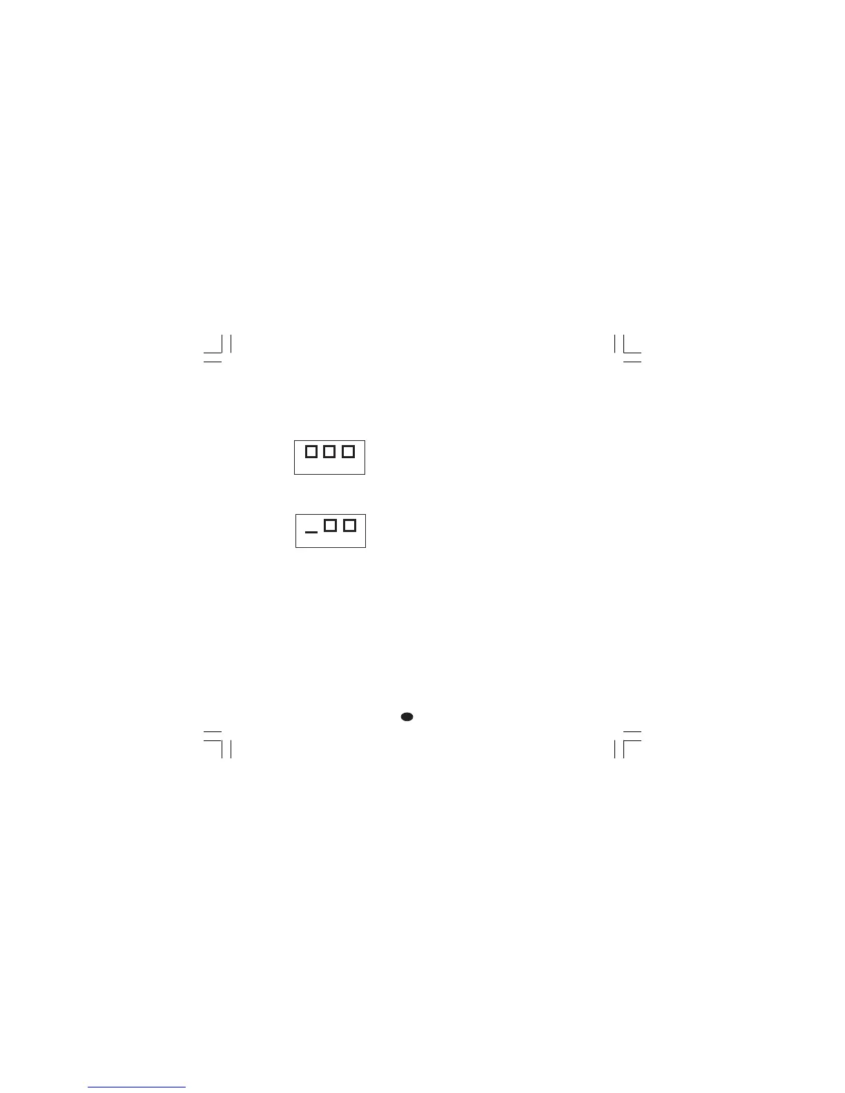
The instrument shows the OVERRANGE
condition with the following indication on the
upper display:
The instrument shows the UNDERRANGE
condition with the following indication on the
upper display:
The sensor leads break can be signalled as:
- for TC input : OVERRANGE or
UNDERRANGE selected by a
solder jumper (see Fig. 12).
- for RTD input : OVERRANGE
Sensor leads short circuit detection:
On RTD input, a special test is provided to signal
OVERRANGE when input resistance is less than
15 ohm (Short circuit sensor detection).
NOTENOTE
NOTENOTE
NOTE: When:
- The instrument is set for one output only and an
OVERRANGE is detected, the OUT 1 turns
OFF (if reverse action) or ON (if direct action).
- The instrument is set for heating/cooling action
and an OVERRANGE is detected, OUT 1 turns
OFF and OUT 2 turn ON.
- The instrument is set for one output only and an
UNDERRANGE is detected, the OUT 1 turns
ON (if reverse action) or OFF (if direct action).
- The instrument is set for heating/cooling action
and an UNDERRANGE is detected, OUT 1
turns ON and OUT 2 turns OFF.
ERRORSERRORS
ERRORSERRORS
ERRORS
Diagnostics are made at instrument switch-on
and during normal mode of operation.
If a fault condition (error) is detected, the lower
display will show the message "Er" while the
upper display shows the relative error code.
ERROR LISTERROR LIST
ERROR LISTERROR LIST
ERROR LIST
100 Write EEPROM error.
150 General hardware error on the CPU card.
200 Tentative to write on protected memory.
201 - 2xx Configuration parameter error. The two
less significant digit’s shown the number
of the wrong parameter (ex. 209 Err show
an Error on P9 parameter)
301 RTD input calibration data error
305 TC input calibration data error
307 RJ calibration data error
310 Current transformer input calibration data
error
400 Control parameters error
500 Auto-zero error.
502 RJ error.
510 Error during calibration procedure.