3
GBGB
GBGB
GB
WIRING GUIDELINESWIRING GUIDELINES
WIRING GUIDELINESWIRING GUIDELINES
WIRING GUIDELINES
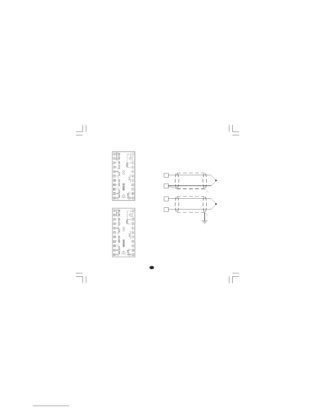
Connections are to be made with the instrument
housing installed in its proper location.
Fig. 3.A TERMINAL BLOCK (for 100/240 V AC
models)
Fig. 3.B TERMINAL BLOCK (for 24 V AC/DC
models)
A) MEASURING INPUTA) MEASURING INPUT
A) MEASURING INPUTA) MEASURING INPUT
A) MEASURING INPUT
NOTENOTE
NOTENOTE
NOTE: Any external components (like zener
barriers etc.) connected between sensor and
input terminals may cause errors in measurement
due to excessive and/or not balanced line
resistance or possible leakage currents.
THERMOCOUPLE INPUTTHERMOCOUPLE INPUT
THERMOCOUPLE INPUTTHERMOCOUPLE INPUT
THERMOCOUPLE INPUT
Fig. 4 THERMOCOUPLE INPUT WIRING
NOTENOTE
NOTENOTE
NOTE:
1) Don’t run input wires together with power cables.
2) For TC wiring use proper compensating cable
preferably shielded
3) If shielded cable is used, it should be grounded
at one point only.
1
3
+
_
1
3
+
_
Shield
Shield