4
GBGB
GBGB
GB
RTD INPUTRTD INPUT
RTD INPUTRTD INPUT
RTD INPUT
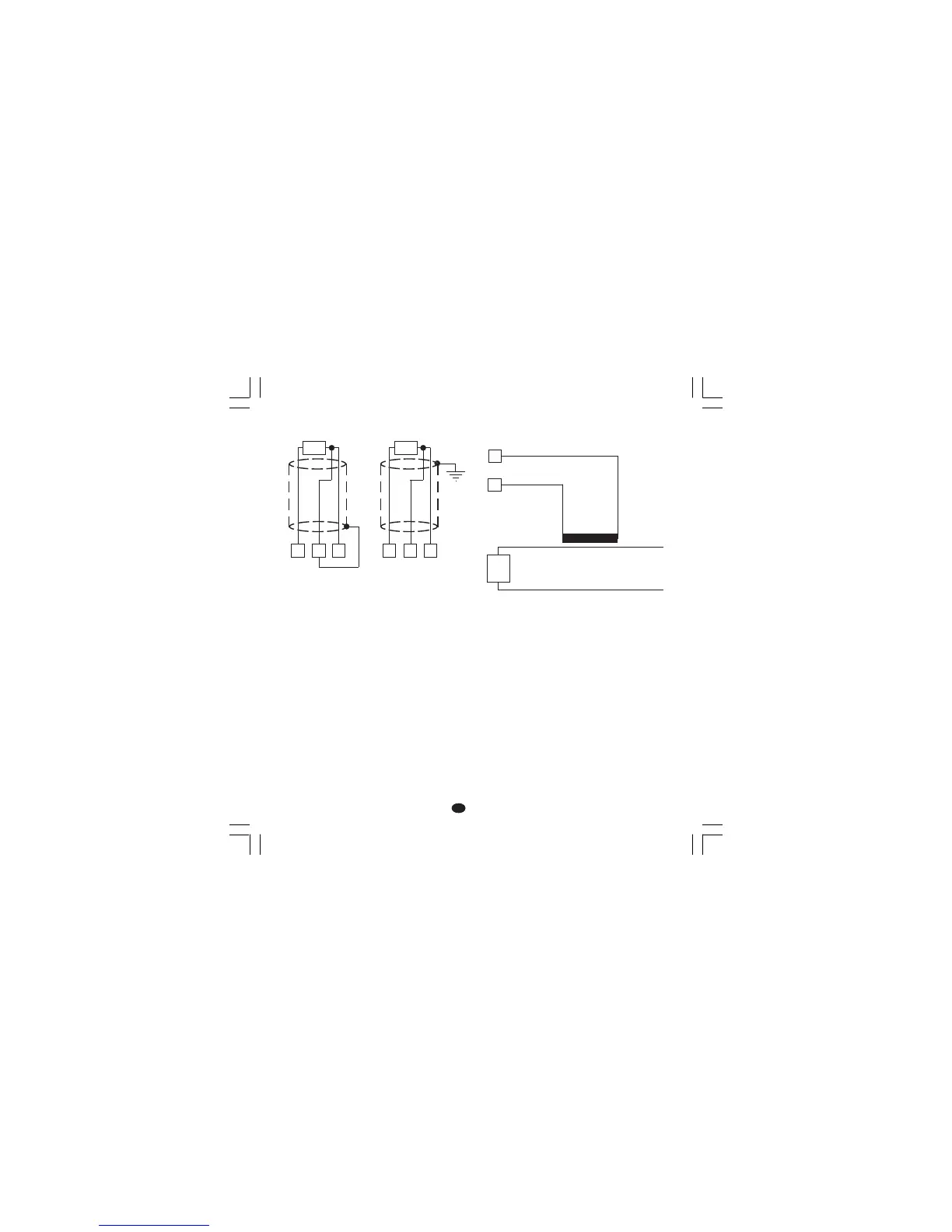
Fig. 5 RTD INPUT WIRING
NOTENOTE
NOTENOTE
NOTE:
1) Don’t run input wires together with power cables.
2) Pay attention to the line resistance; a high line
resistance (higher than 20 Ω/wire) may cause
measurement errors.
3) If shielded cable is used, it should be grounded
at one point only.
4) The resistance of the 3 wires must be the
same.
B) CURRENT TRANSFORMER INPUTB) CURRENT TRANSFORMER INPUT
B) CURRENT TRANSFORMER INPUTB) CURRENT TRANSFORMER INPUT
B) CURRENT TRANSFORMER INPUT
Fig. 6 CURRENT TRANSFORMER INPUT
WIRING
Note:
1) The input impedance is equal to 10 Ω.
2) the maximum input current is equal to 50 mA
(50 / 60 Hz).
4
RTD
13 4
RTD
13
6
7
Current
transformer
Load