6
GBGB
GBGB
GB
In these cases it is recommended to install an
additional RC network across the external contact
(or close to the non protected contact of the
instrument) as shown in Fig. 8.
The capacity (C) and resistive (R) values are
shown in the following table.
The cable involved in relay output wiring must be
as far away as possible from input or communica-
tion cables.
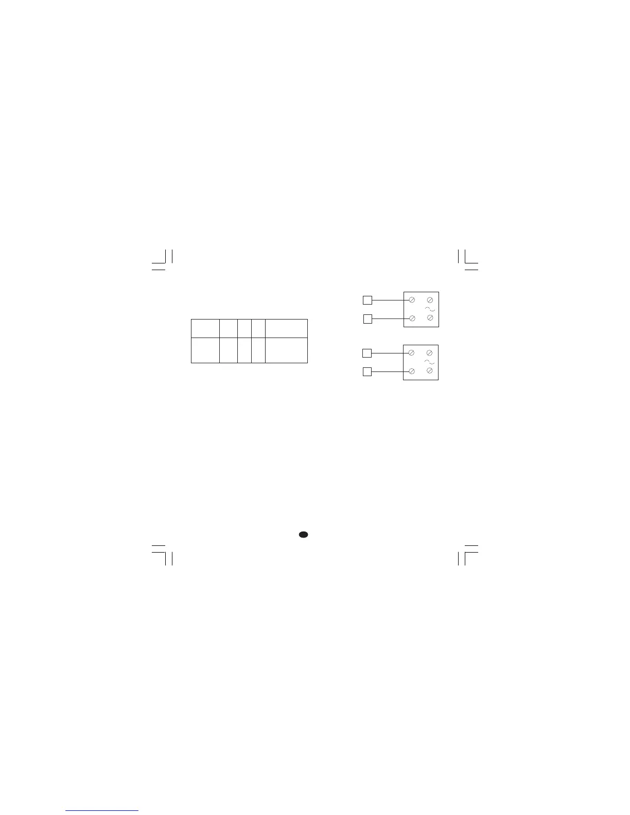
D) LOGIC OUTPUT FOR SSR DRIVED) LOGIC OUTPUT FOR SSR DRIVE
D) LOGIC OUTPUT FOR SSR DRIVED) LOGIC OUTPUT FOR SSR DRIVE
D) LOGIC OUTPUT FOR SSR DRIVE
Fig. 9 SSR DRIVE OUTPUT WIRING.
These are time proportioning outputs.
Logic level 0Logic level 0
Logic level 0Logic level 0
Logic level 0: Vout < 0.5 V DC.
Logic level 1Logic level 1
Logic level 1Logic level 1
Logic level 1:
- 14 V
+ 20 % @ 20 mA
- 24 V
+ 20 % @ 1 mA.
Maximum current = 20 mA.
NOTESNOTES
NOTESNOTES
NOTES:
1) These outputs are not isolated.
A double or reinforced isolation between instru-
ment output and power supply must be assured
by the external solid state relay.
2) Relay output and SSR drive output are both
available. When a SSR output is desired it is
necessary to enable the relay output and
viceversa (see chapter "Preliminary hardware
settings").
LOAD
(mA)
<40 mA
<150 mA
<0.5 A
C
(µF)
0.047
0.1
0.33
R
(Ω)
100
22
47
P.
(W)
1/2
2
2
OPERATING
VOLTAGE
260 V AC
260 V AC
260 V AC
Solid state relay
Solid state relay
_
+
_
+
_
_
+
+
18
19
14
15
OUT 1
OUT 2
(AL1/Cool.)