EasyManua.ls Logo

ESAB Aristo Mig 3001i User Manual

ESAB Aristo Mig 3001i
76 pages
To Next Page IconTo Next Page
Page #1 background imageLoading...
Page #1 background image
0740 800 196 Valid for serial no. 833-xxx-xxxx to 039-xxx-xxxx101019
Aristo Origo
Mig 3001i
Tig 3001i
Service manual

Table of Contents

Question and Answer IconNeed help?

Do you have a question about the ESAB Aristo Mig 3001i and is the answer not in the manual?

ESAB Aristo Mig 3001i Specifications

General IconGeneral
Output Current Range30 - 300 A
Output Current300 A
Duty Cycle60 % at 300 A
Cooling TypeForced air
Wire Diameter Range0.8 - 1.2 mm
Protection ClassIP23
Input Voltage3 x 400 V

Summary

Design Structure of the Power Source

15 Power Module

Function of the Power module (dual forward inverter).

20 Processor Board Module (Controller Module)

Function of the Processor board module (monitoring and control).

TECHNICAL DATA

Component Description

10AP1 TIG Board

DESCRIPTION OF OPERATION

2AP1 Interference Suppressor Board and Main Rectifier

15 The Power Module

15AP1 Power Board

15AP1:3 Overvoltage and Undervoltage Protection

15AP1:5 Gate Driver Stages and Switching Circuits

15AP2 Secondary Board

20AP1 Control Board

20AP1:3 The CAN Bus

Communication Interruptions

20AP1:9 Arc Voltage Feedback

Open-Circuit Voltage Control

20AP2 Relay Board

FAULT CODES

Summary of Fault Codes

Table summarizing fault codes and affected units.

Fault Code Description

Power Source

Fault code descriptions specific to the power source.

SERVICE INSTRUCTIONS

ESAT Service Kit

Checking Power Board 15AP1

Checking Secondary Board 15AP2

Checking the Diode Modules

Procedure for checking diode modules.

Soft Starting

Mounting Components on the Heat Sink

Power Board 15AP1 with Semiconductor Modules

Diode Modules 15D1, 15D2 and Secondary Board 15AP2

Calibrating the Current Sensor Signal

MIG Power Sources, Calibration of the Arc Voltage Feedback

TIG Power Sources, Calibration of the Arc Voltage Feedback

IN-SERVICE INSPECTION AND TESTING

Periodic Inspection and Test

Steps for periodic inspection and testing.

After Repair, Inspection and Test

Steps for inspection and testing after repair.

Visual Inspection

Electrical Test

Check the No-Load Voltage

Procedure for checking no-load voltage.

Check of No-Load Voltage with the VRD Activated

Checking no-load voltage with VRD active.

Functional Test

Test Report

SAFETY

INSTALLATION

Mains Power Supply

Requirements and considerations for the mains power supply.

OPERATION

Connections and Control Devices Mig 3001i

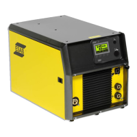
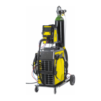
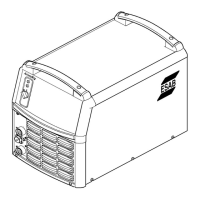
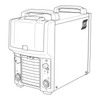
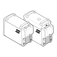
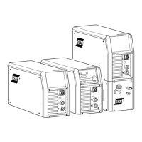
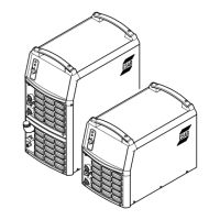
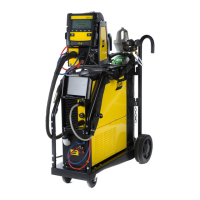
Description of connections and controls for Mig 3001i.

Connections and Control Devices Tig 3001i

Overheating Protection

MAINTENANCE

FAULT-TRACING

Related product manuals