5 OPERATION
0446 253 101
- 16 -
© ESAB AB 2020
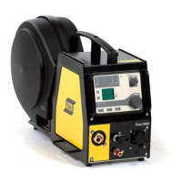
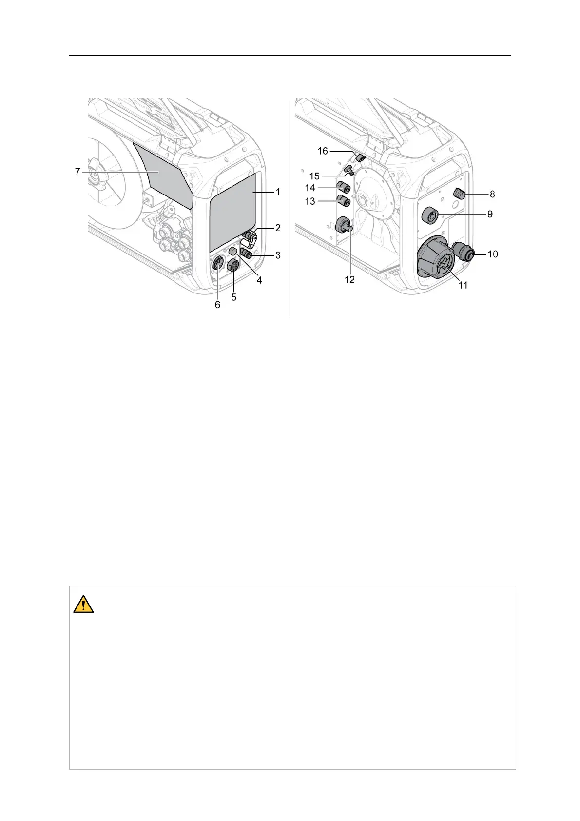
5.2 Connections and control devices
1. External control panel (see the
"CONTROL PANEL" chapter)
9. Connection for MMA welding torch
(OKC)
3)
(only on product variants with
MMA)
2. Connection BLUE for cooling liquid to
the welding torch, with ELP
1)
(only on
product variants with ELP)
10. Wire inlet for use with Marathon Pac™
(optional)
3. Connection RED for cooling liquid from
the welding torch
11. Interconnection strain relief for cables
from power source
4. Connection for Tweco trigger cable
(only in combination with Tweco torch)
12. Connection for welding current from
power source (OKC)
5. Connection for remote control unit
(optional)
13. Connection RED for cooling liquid to the
power source (the cooling unit)
6. Connection for MIG/MAG welding torch
(Euro or Tweco type)
2)
14. Connection BLUE for cooling liquid from
the power source (the cooling unit)
7. Internal control panel (see the
"CONTROL PANEL" chapter)
15. Connection for shielding gas
8. Heat kit switch (Offshore variants) 16. Connection for control cable from power
source
1)
ELP = ESAB Logic Pump (see the "Cooling liquid connection" section)
WARNING!
The right and left side doors of the wire feed unit must be closed when welding
and/or wire feeding occurs. Never weld or feed the wire without having closed both
doors!
2)
Electrical hazard! During MIG/MAGwelding, the MMA electrode should be
removed from the electrode holder and must be kept away from the work piece and
any other current leading material. If possible, the electrode holder should be
removed from the welding unit OKC connector and the connector should be covered
with an isolating cap.
3)
Electrical hazard! During MMAwelding, the wire stick out should be cut to
minimize the possibility of unintentional contact by the MIG/MAG torch. The torch
must be kept away from the work piece and any other current leading material!