-- 6 --
cmha2de1
V01, V02 Mains rectifier diode bridge, 35 A, 1200 V. After r eplacing the rectifier
bridges, the machine must be soft--started: see instructions on page 25.
Rectifier bridge V02 is only mounted in LHN 200.
V03, V04 Rectifier and freewheel diodes.
V03 r ectifies the welding current.
During the time interval between two voltage pulses from transformer
TC02, the freewheel diodes V04 maintain the welding current from
inductor L01.
Before serial number 628--xxx--xxxx:
V03 consists of six parallel--connected diodes, and V04 consists of eight
parallel--connected diodes. V03 and V04 are mounted on the same cooling
fins. If any of the diodes is/are faulty, the entire cooling fin unit must be
replaced, as the diodes are soldered to it. For spare parts see the spare parts
list item 430 (LHN 140/200) and item 830 (LHN 130)
From serial number 628--xxx--xxxx:
A new r ectifier unit is introduced. On the cooling fins in LHN 130/140 is
one diode module mounted and in LHN 200 are two diode modules
mounted. Each diode module has two diodes.
See page 27 for fitting instructions.
V05 LED, yellow.
Lit when thermal overload cutout ST01 opens due to high temperature.
V06 Diode: see L02. Not mounted in LHN 130.
X01 Mains terminal block: 4-- pole or 8--pole respectively. Replaced by circuit
board AP05 from serial no. 540--xxx--xxxx.
XS01--XS13 Sleeve connectors.
XS11 LHN 140/200: 12--pole connector for connection of remote control unit.
XS12 Welding terminals (2 -- OKC connectors).
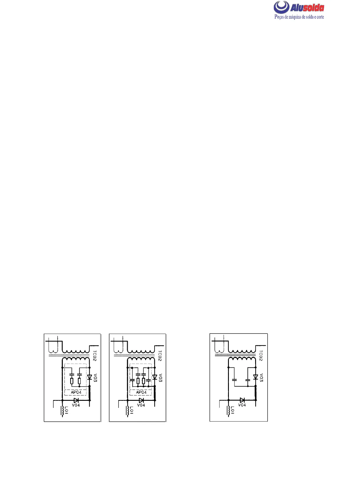
TRANSIENT PROTECTION, RECTIFIER UNIT V03, V04
C06
LHN 130/140 LHN 200
before serial number 628--xxx--xxxx
LHN 130/140/200
with serial number 628--xxx--xxxx
and 220--xxx--xxxx
 Loading...