-- 1 9 --
dia3d1ea
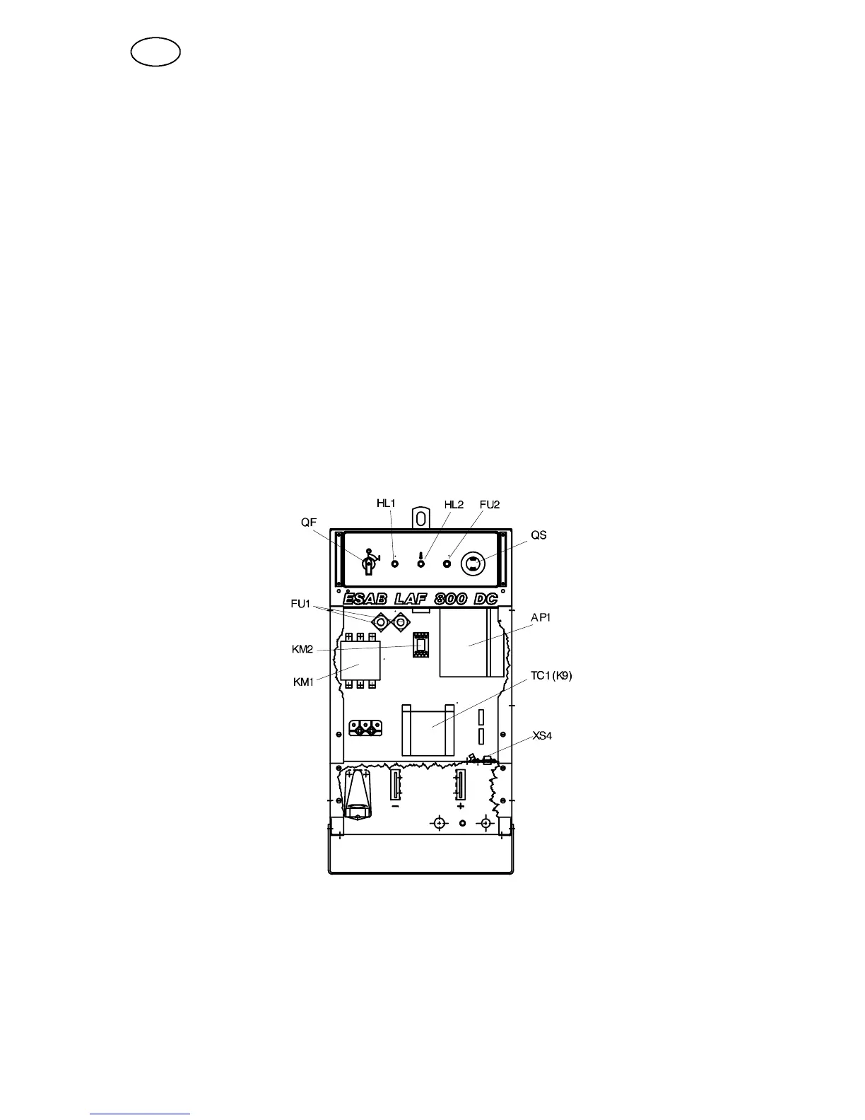
S Drill the holes according to the drilling diagram for the attachment of
-- the fuse --bases (FU1)
-- the electronics board (AP1)
-- the contactor (KM2)
-- the discharging board with the 12--pole contact device (XS4).
S Fit a new (AP1) circuit board with box on the plate, using the insulating washers
and self --tapping screws which form part of the conversion kit.
S Connect the discharge capacitor to earth.
S Set the two DIP switches (SW1 and SW2) on the board according to the
instructions in the LAF manual.
S Fit the 12--pole contact (XS4) and the discharging board on the medium plate.
S Connect a new cable stem according to the connection diagram.
S Mount the cables for the emergency stop on the control panel. Then connect the
control panel to the cable stem.
S Remove (cut off) the conductor 077 between the board K45.3 and the collector
rail.
S Only remount the RC filter fitted in the old power source.
S Remove the old connection diagram on the inside of the cover plate.
GB