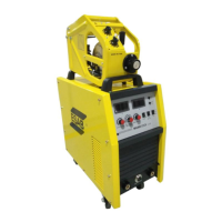
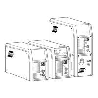
The ESAB MIG400iCCCV is an inverter-based welding power source designed for both MIG (Metal Inert Gas) and MMA (Manual Metal Arc) welding operations. This instruction manual provides comprehensive guidance for the installation, operation, and general maintenance of the device, ensuring safe and efficient use.
Function Description
The MIG400iCCCV serves as a versatile welding power source, capable of delivering stable and controlled welding current and voltage for various applications. In MIG mode, it facilitates continuous wire feeding, making it suitable for high-productivity welding tasks. The MMA mode, on the other hand, is ideal for welding with coated electrodes, offering flexibility for different material types and thicknesses. The inverter technology employed in this device ensures a compact design, energy efficiency, and precise control over welding parameters, leading to superior weld quality.
Usage Features
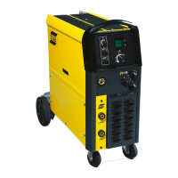
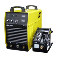
The operation of the MIG400iCCCV is designed to be user-friendly, with clear controls and indicators. The front panel features a current meter and a voltage meter, allowing the operator to monitor welding parameters in real-time. Crater Current and Crater Voltage controls are available for fine-tuning the arc at the end of a weld, which helps in filling craters and improving the overall weld quality. The MMA/MIG switch allows for easy selection between the two welding modes. For MIG welding, a dedicated wire feeder control circuit socket is provided, along with a power socket. Additional controls include Current Inductance control, Welding mode selection switch, and Crater OFF/ON (2T/4T) selection switch, offering comprehensive control over the welding process.
On the rear panel, the device includes a power switch, a heater socket (AC110V) for CO2 gas, a controlling power trip (3A) for safety, and a fan for cooling. An earthing bolt ensures proper grounding, and a cable fixed head along with the power input cable facilitates connection to the main power supply. A nameplate provides essential identification details of the machine.
The indicating lights on the front panel provide crucial status information. A green light indicates that the power is on. If both green and red lights are illuminated, it signifies that the machine is overheated. The device is designed to automatically return to normal working condition once the internal temperature drops to an acceptable level, preventing damage from overheating.
In MIG mode, the device offers several advanced features to enhance welding performance. The Crater Control (2T/4T) function allows operators to adjust the crater voltage and current at the end of a weld. This helps in filling the crater with an arc ending current (typically 40%-70% of the welding current), thereby improving the quality of the weld. The 2T/4T selection switch further dictates the operation mode, providing flexibility for different welding techniques.
Soft wire feeding is another notable feature, designed to achieve satisfying welding quality. Before the wire touches the workpiece, the machine feeds the wire at a preset low speed. Once the arc is struck, the wire feeding speed increases to the normal level. This mechanism improves the success rate of arc striking and ensures a reliable and stable arc. If current is not detected during this initial stage, it indicates a failure in arc striking.
The burn back time feature addresses the issue of wire sticking to the workpiece after the torch trigger is released. Due to inertia, the wire continues to feed for a short period. The burn back function maintains an output voltage for a specific duration, allowing the wire to burn back and prevent it from sticking, thus facilitating the next weld.
Current Inductance control, often referred to as an electronic reactor, allows for adjustment of the wire burning power by changing the current changing speed. This feature helps in reducing spatter, leading to cleaner and more efficient welds.
Ball cutting is an automatic function designed to eliminate the large droplet that typically forms at the end of the wire after welding. This droplet, often accompanied by slag, can make subsequent arc striking difficult. The ball cutting circuit automatically cuts this droplet, ensuring a clean wire end for the next weld.
Finally, a 3-second post-gas time is set in MIG mode to protect the welding area after the arc is extinguished. This continuous flow of shielding gas prevents atmospheric contamination of the hot weld pool, ensuring a high-quality finish.
For MMA mode, the operation is simplified. The operator needs to switch the MMA/MIG selector on the power source to MMA mode. The welding current can then be easily adjusted using the MMA current setting knob located on the power source.
Maintenance Features
The manual emphasizes the importance of regular maintenance and troubleshooting to ensure the longevity and optimal performance of the MIG400iCCCV. Safety precautions are paramount, and only trained personnel should carry out maintenance work.
The troubleshooting section provides a structured approach to identifying and resolving common issues. For instance, if the protecting indicating light is ON, it could mean the thermal relay is broken or the machine is overheated. The suggested solutions include replacing the thermal relay or restarting the work once the temperature normalizes. If the fan doesn't work, it might be defective or its lead disconnected, requiring replacement or reconnection.
Issues with meters not displaying values could be due to disconnected leads or a defective main control PCB, necessitating reconnection or PCB replacement. If the current knob doesn't work, the lead might be disconnected or the potentiometer broken, requiring reconnection or replacement. A broken fuse (1A) is a common cause for various malfunctions and should be checked and replaced if necessary.
If the machine doesn't work after pressing the torch trigger, it could indicate a defective torch trigger or that the machine is tripping due to exceeding its duty cycle. Solutions include connecting the control cable to the torch switch or working under a suitable duty cycle. A broken control PCB is also a possibility, requiring replacement.
Problems with wire feeding can stem from a disconnected control cable, a broken fuse on the back of the machine, a defective wire feeder motor, or a defective control PCB. The manual advises reconnecting the control cable, replacing the fuse, repairing/replacing the motor, or replacing the control PCB as appropriate.
No OCV (Open Circuit Voltage) could be caused by overvoltage, voltage lack, lack of phase, or an overheated machine. The solutions involve restarting the work when voltage returns to normal, or when the temperature normalizes. A defective power switch or a broken fuse (1A) are also listed as potential causes, requiring replacement.
Finally, if there is no gas flow, the gas hose might be disconnected, staved, or jammed, or the solenoid could be defective. The recommended actions are to reconnect the gas hose, check the gas route, or repair/replace the solenoid.
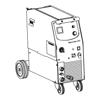
The manual also provides an exploded view and parts list, which are invaluable for identifying specific components during repair or replacement. This detailed breakdown allows for precise ordering of parts and facilitates efficient maintenance by authorized service personnel. Adherence to the installation guidelines, such as providing adequate ventilation and maintaining proper clearances, also contributes to the overall reliability and reduces the need for frequent maintenance.