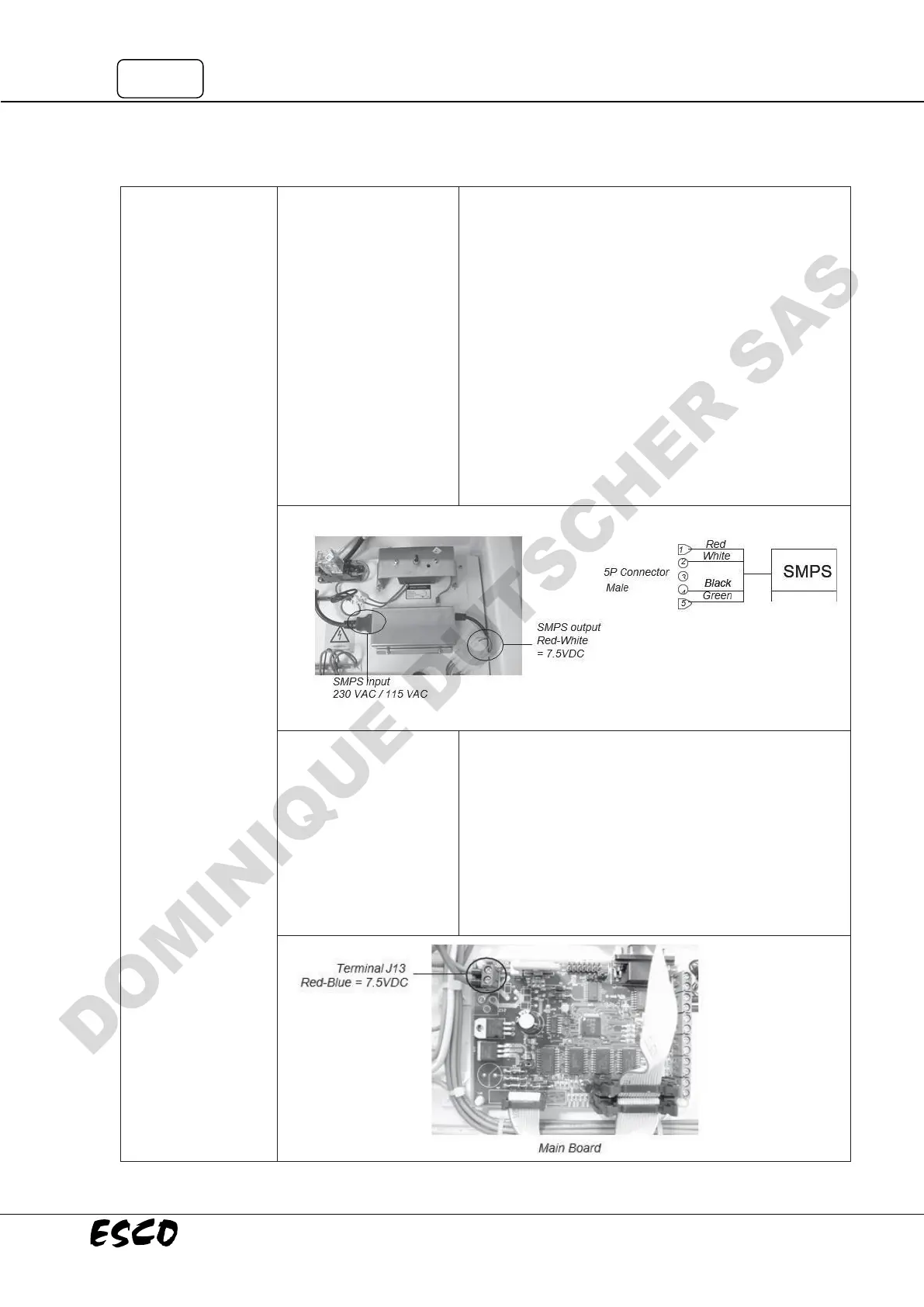
• Unit must be turned on to perform this test.
• See Layout A at the end of this section to locate the SMPS.
It is inside the electrical panel and covered by a stainless
steel box.
• Checking SMPS output: Disconnect the 5-pin connector
attached to the SMPS output then measure the DC
voltage between Red (pin 1) and White (pin 2) cables on
the SMPS side (see Fig. 1.7).
• The voltage should be in range of +7.5 VDC ± 10%.
• If out of range, please check incoming power to the SMPS
Molded cord into SMPS — check terminal where the cord
is connected. The input of SMPS should be 230 VAC ±10%
for PCR-XA1/3 or 115 VAC ± 10% for PCR- XA2/4. If input
is correct but output is not, then replace the SMPS.
Cabinet does not
start (LCD, button,
fan, light, and UV
Connection problem to
main board
(for PCR only)
• See Layout A at the end of this section to locate the main
board at electrical panel.
• Measure the incoming voltage on the Main Board at
terminal J13 (Note polarity, BLUE wire closest to edge is
negative). See Fig. 1.9 below to locate terminal J13.
• Voltage should be between 6.75 – 8.25 VDC.
• If voltage is out of range, check connection between
SMPS and main board.
• If voltage is correct, proceed to next step.