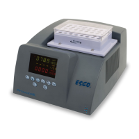
• See Layout A at the end of this section to locate the
fluorescentballast, connector B, and relay board inside
electricalpanel.
• Turn on the cabinet by connecting to the main supply, then
turn on the light by pressing LIGHT button on
membrane/keypad.
• Check AC voltage at ballast input (between pin NO on J13
terminal on relay board to neutral), see Fig. 8.1below.
• It should be 230 VAC ± 10% for 230 V cabinets or 115 VAC
± 10% for 115 V cabinets.
• If not, check the LS7 relay and F7 fuse (refer to possible
cause Faulty relay or fuse below).
For SCR:
• See Layout B at the end of this section to locate the
fluorescent ballast and connector B inside electrical panel.
• Turn on the cabinet by connecting to the main supply, then
switch on the light with the LIGHT rocker switch on control
panel.
• Check AC voltage at ballast input (between pin connector
A-5 to neutral). It should be 230 VAC ± 10% for 230 V
cabinets or 115 VAC ± 10% for 115 V cabinets.