• Unplug the cabinet from the main supply.
• Open the top access cover and locate electrical panel
behindit.
• See Layout A at the end of this section to locate the relay
board, UV ballast, and connector B at electricalpanel.
• Check for any loosed or bad connection between relay
board, UV lamp ballast and female connector B.
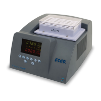
• See Fig. 9.4 to locate terminal J15 on relay board, check
tightness of 2 cables connected to J15.
• For connector B, disconnect the male side from electrical
panel, then check male and female side for any bad
connection.
• Check also connection of the UV lamp holder (see Fig. 7.3).
For SCR:
• Unplug the cabinet from the main supply.
• Open the top access cover and locate electrical panel
behindit.
• See Layout B at the end of this section to locate the relay K1,
K2, and K3, UV ballast, and connector B at electrical panel.
• Check for any loose or wrong connection between relays,
UV lamp ballast and female connector B (see Fig. 9.5).
• For connector B, disconnect the male side from
electrical panel, then check male and female side for
any loose or bad connection.
• Check also connection of the UV lamp holder (see Fig. 7.3).