Overview
1. Overview
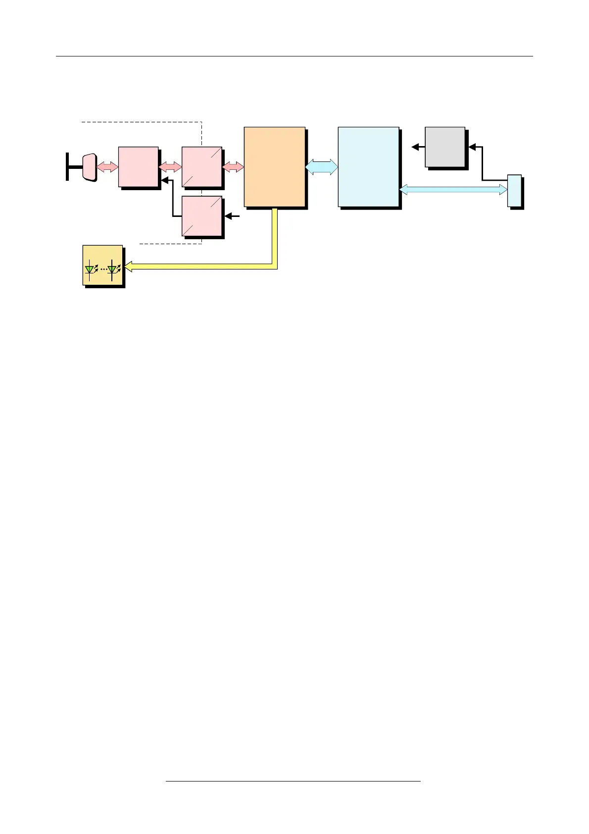
Figure 1: Block-circuit diagram of CAN-USB/2 module
The CAN-USB/2 module is an intelligent CAN interface with an ARM7 micro controller for local
CAN data management. The module supports the USB 2.0 Hi-Speed interface with data transfer
rates of 480 Mbit/s.
The ISO 11898-compliant CAN interface allows a maximum data transfer rate of 1 Mbit/s. Like
many other features of CAN interfaces, the bit rate can be set by means of software. CAN interface
and other voltage potentials are electrically isolated by means of a digital isolator and DC/DC
converters.
The supply voltage is fed via the USB bus. The module is equipped with four green LEDs in the
front panel which indicate the current module status.
Page 8 of 28
Hardware Manual • Doc. No.: C.2066.21 / Rev. 1.6
CAN-USB/2