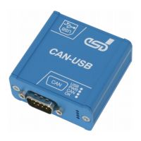
Case View with LED and Connector Description
2.1 LED-Displays
LED
NAME Number Status
Description
USB LED300D on
USB module is enumerated
(a node-ID is assigned to the USB module)
Power LED300C on
module is in operation,
the 5 V power supply is applied to the module
CAN LED300B on data is received or send on the CAN bus
OK LED300A
on CAN interface is initialized, bit rates are set
off bit rate not set
fast flashing
(approx. 10 Hz)
CAN interface is initialized and in mode “Listen Only”,
the bit rate is already set
slow flashing
(approx. 1 Hz)
CAN interface is initialized and in mode “Automatic
Baud rate Detection” (from firmware version 1.0.0.4
and CAN driver version 2.5.2 on)
Table 1: Description of LED display
Page 10 of 28
Hardware Manual • Doc. No.: C.2066.21 / Rev. 1.6
CAN-USB/2