Appendix 217
The submix bus selection can be programmed by Zone in the Dynamic
Processing, Channel Assignment screen. These settings can be overwrit-
ten in the Master by changing the submix setting from “Z” (Zone) to
“Main, Sub 1, 2 or 3” which routes the preset on that MIDI channel to
the selected submix bus.
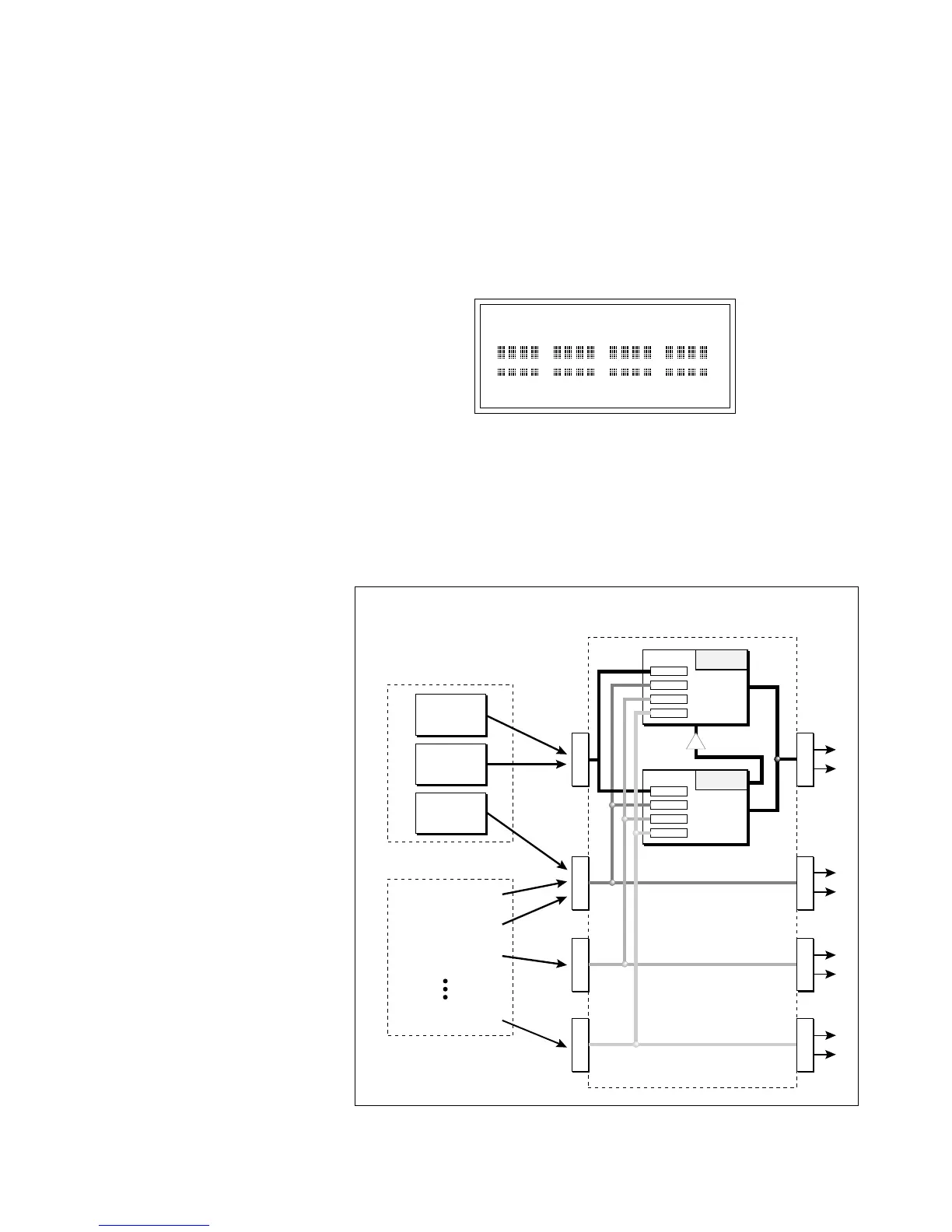
In the screen below, MIDI channel 4 is programmed to the submix 1
bus. MIDI channels 2, 3 and 5 obey the submix routing as programmed
in each zone.
MIX C=01 VOLUME=127
zzz1 zzzz zzzz zzzz
The submix bus routings are also available at the Submix jacks on the
rear panel. Note that these outputs contain only Dry signal. The Effects
Processors are ONLY connected to the FX Outputs.
If a plug is inserted into a Sub Output jack, the dry signal from that bus
is removed from the effects processor. This feature allows you to have
three dry mixes from the Sub Outputs and an “Effects Only”␣ mix from
the Main Outputs.
Master/Global,
MIDI (9), MIDI Mix (1).
! Caution:
You must be in Multimode in
order to change channels in the MIDI Mix
screen.
The diagram above shows how individual voices or MIDI channels can be routed to the four busses.
Note that the signal lines represent stereo signals.
M
A
I
N
S
U
B
1
S
U
B
2
S
U
B
3
S
U
B
1
F
X
OUTPUT SECTION
& EFFECTS PROCESSORS
ZONE
MIDI Channel 1
MIDI Channel 2
MIDI Channel 3
MIDI Channel 16
By ZONE
By MIDI CHANNEL
ZONE
ZONE
S
U
B
2
S
U
B
3
FX Sends
Main 15%
Sub 1 10%
Sub 2 0%
Sub 3 0%
Hall 1
Effect
A
FX Sends
Main 0%
Sub 1 0%
Sub 2 25%
Sub 3 30%
Chorus
Effect
B
B➟A