CONFIDENTIAL
2 Schematic Checklist
During the chip’s system reset (power-on-reset, RTC watchdog reset, brownout reset, analog super watchdog
reset, and crystal clock glitch detection reset), the latches of the strapping pins sample the voltage level as
strapping bits of “0” or “1”, and hold these bits until the chip is powered down or shut down.
GPIO0, GPIO45 and GPIO46 are connected to the chip’s internal weak pull-up/pull-down during the chip reset.
Consequently, if they are unconnected or the connected external circuit is high-impedance, the internal weak
pull-up/pull-down will determine the default input level of these strapping pins.
GPIO3 is floating by default. Its strapping value can be configured to determine the source of the JTAG signal
inside the CPU, as shown in Table 4. In this case, the strapping value is controlled by the external circuit that
cannot be in a high impedance state. Table 3 shows more configuration combinations of
EFUSE_DIS_USB_JTAG, EFUSE_DIS_PAD_JTAG, and EFUSE_STRAP_JTAG_SEL that determine the JTAG
signal source.
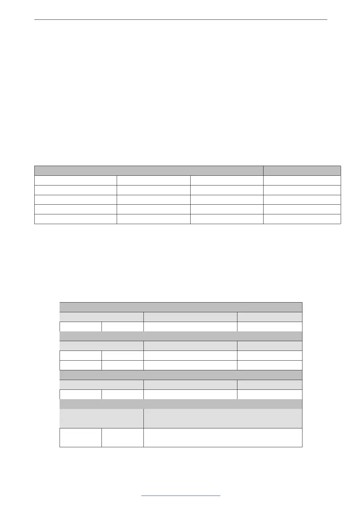
Table 3: JTAG Signal Source Selection
EFUSE_STRAP_JTAG_SEL EFUSE_DIS_USB_JTAG EFUSE_DIS_PAD_JTAG JTAG Signal Source
1 0 0 Refer to Table 4
0 0 0 USB Serial/JTAG controller
don’t care 0 1 USB Serial/JTAG controller
don’t care 1 0 On-chip JTAG pins
don’t care 1 1 N/A
To change the strapping bit values, users can apply the external pull-down/pull-up resistances, or use the host
MCU’s GPIOs to control the voltage level of these pins when powering on ESP32-S3.
After reset, the strapping pins work as normal-function pins.
Refer to Table 4 for a detailed configuration of the strapping pins.
Table 4: Strapping Pins
VDD_SPI Voltage
1
Pin Default 3.3 V 1.8 V
GPIO45 Pull-down 0 1
Booting Mode
2
Pin Default SPI Boot Download Boot
GPIO0 Pull-up 1 0
GPIO46 Pull-down Don’t care 0
Enabling/Disabling ROM Messages Print During Booting
3 4
Pin Default Enabled Disabled
GPIO46 Pull-down See the fourth note See the fourth note
JTAG Signal Selection
Pin Default
EFUSE_DIS_USB_JTAG = 0, EFUSE_DIS_PAD_JTAG = 0,
EFUSE_STRAP_JTAG_SEL=1
GPIO3 N/A
0: JTAG signal from on-chip JTAG pins
1: JTAG signal from USB Serial/JTAG controller
Espressif Systems 14
Submit Documentation Feedback
ESP32-S3 Series Hardware Design Guidelines v1.0
 Loading...


