EasyManuals Logo

Espressif ESP32 User Guide

Espressif ESP32
20 pages
To Next Page IconTo Next Page
To Previous Page IconTo Previous Page
Page #14 background imageLoading...
Page #14 background image
2. Getting Started
Result
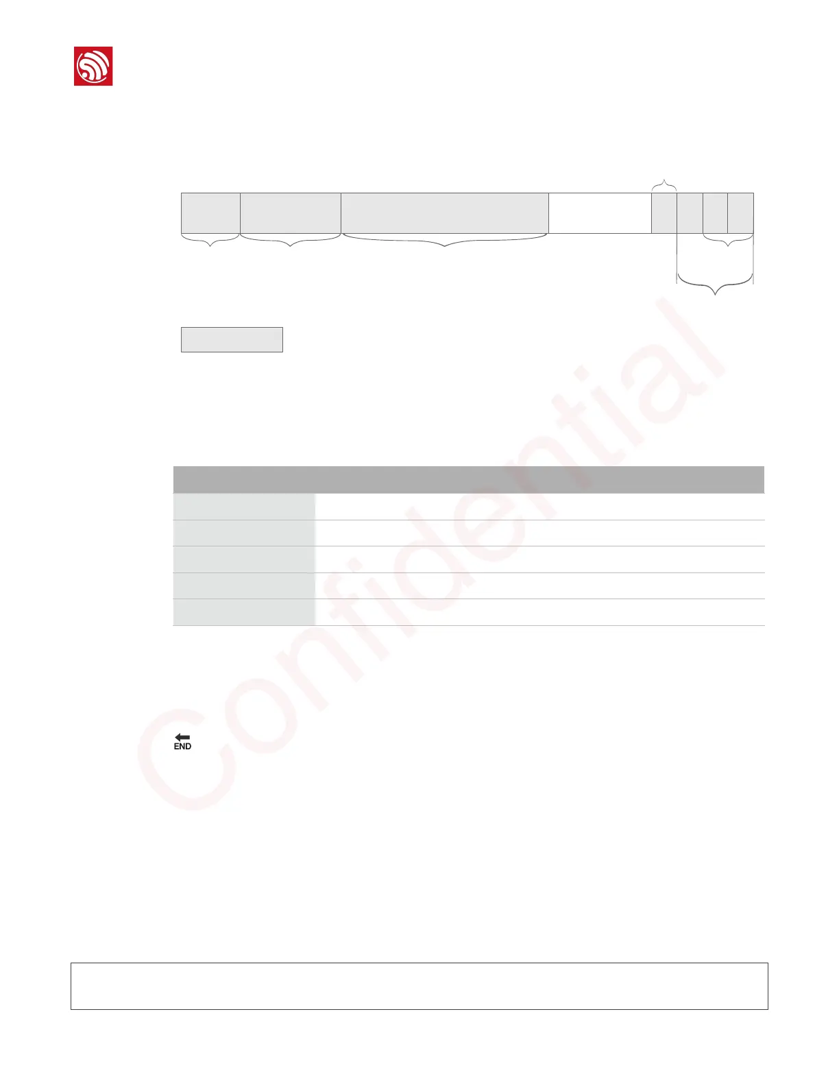
The flash layout is shown as Figure 2-3.
For the flash usage, refer to Table 2-5.
2.1.5.
Running Application
1.
Power off and switch the hardware to the running mode.
2.
Power on the hardware and run the application.
🔚
2.2.
SSC Command Reference
Here lists some common Wi-Fi commands for you to test the board.
2.2.1.
op
Description
op commands are used to set and query the Wi-Fi mode of the system.
Example
op -Q
Figure 2-3. Flash Layout
16K
boot.bin
240K
irom1.bin irom0_flash.bin
3840K
esp_init_data_default.bin
4K 4K 4K
blank.bin
System Parameter
Available segment
4K
Table 2-5. Flash Usage
Segment Name
Start Address
Length
dport0_0_seg
org = 0x3FF00000
len = 0x10
dram0_0_seg
org = 0x3FFD8000
len = 0x24000
iram1_0_seg
org = 0x40040000
len = 0x20000
irom0_0_seg
org = 0x40080010
len = 0x37FFF0
irom0_1_seg
org = 0x3FE04010
len = 0x3BFF0
Espressif
2015.12
Confidential

Other manuals for Espressif ESP32

Questions and Answers:

Question and Answer IconNeed help?

Do you have a question about the Espressif ESP32 and is the answer not in the manual?

Espressif ESP32 Specifications

General IconGeneral
Clock SpeedUp to 240 MHz
SRAM520 KB
Wi-Fi802.11 b/g/n
BluetoothBluetooth v4.2 BR/EDR and BLE
GPIO Pins34
Operating Voltage2.2V to 3.6V
Operating Temperature-40°C to +125°C
ProcessorTensilica Xtensa LX6
Flash Memory4MB (varies by module)
ADC12-bit SAR ADC up to 18 channels
DAC2 channels of 8-bit DACs
I2C2 x I2C
I2S2 x I2S
InterfacesCAN 2.0
SPI4 SPI interfaces
UART3 x UART

Related product manuals