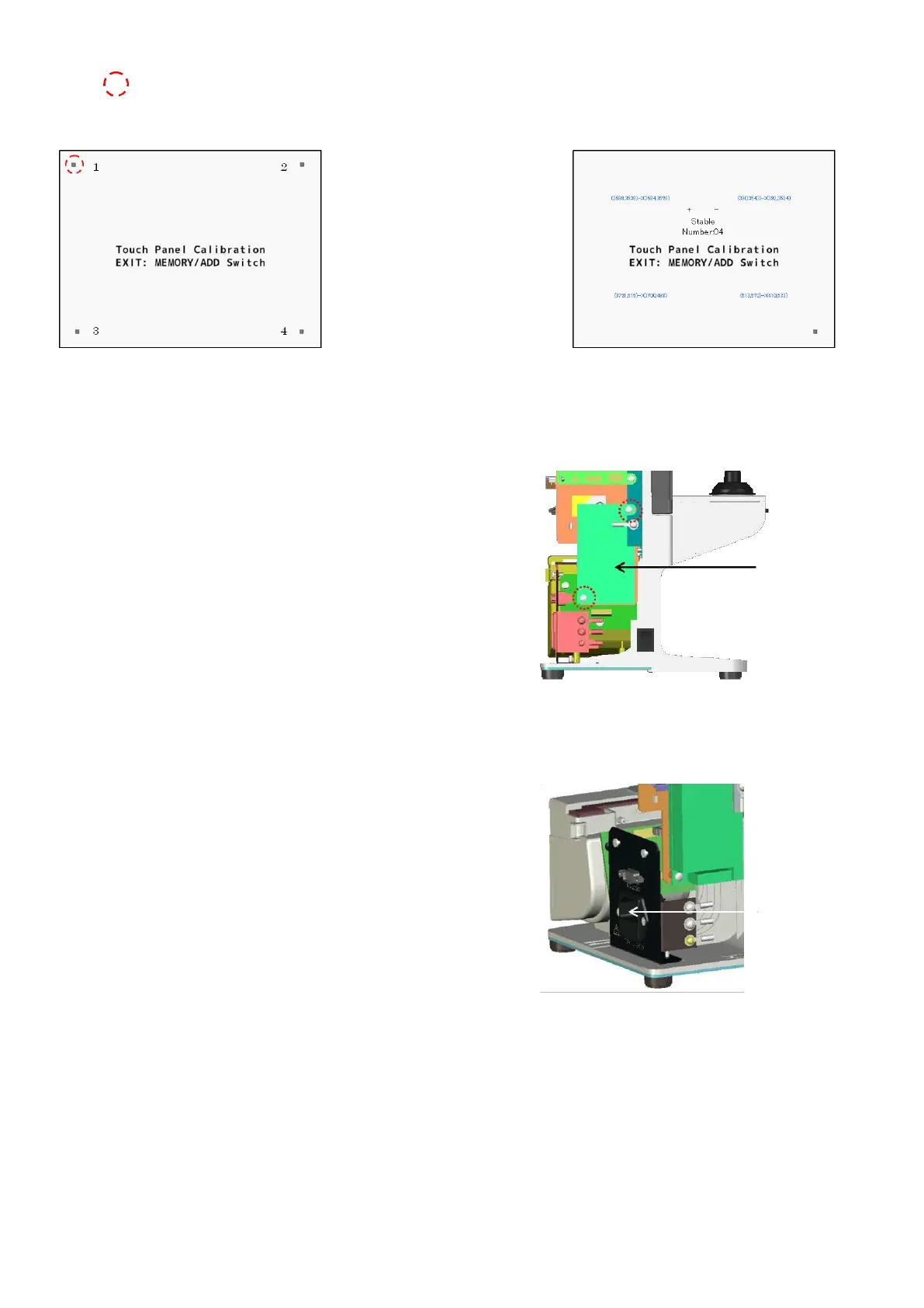
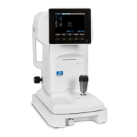
Match the switch position and coordinates of touch panel.
Touch
There are 4 areas to touch in order.
It is completed after touching 4 areas.
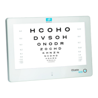
5.4. Switching power supply
Remove the back cover.
(Refer to ‘4. Assembly and Disassembly of External Facing’.)
Disconnect the harnesses connected to the switching power
supply.
Replace it by unscrewing 2 screws (cross-recessed bind screw
M3×5) fixing the switching power supply.
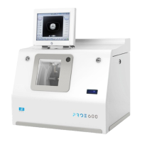
5.5. Power supply inlet
Remove the back cover. (Refer to ‘4. Assembly and Disassembly
of External Facing’.)
Disconnect the harnesses connected to the power supply inlet.
Unscrew 2 screws (cross-recessed flat screw M3×5).
Pull out the power inlet and replace the harnesses.
(
※
Press the connector on the side of power inlet when pulling
out the power inlet.)