5.9. Light projecting unit assy.
Remove the back cover and top cover.
(Refer to ‘4. Assembly and Disassembly of External Facing’.)
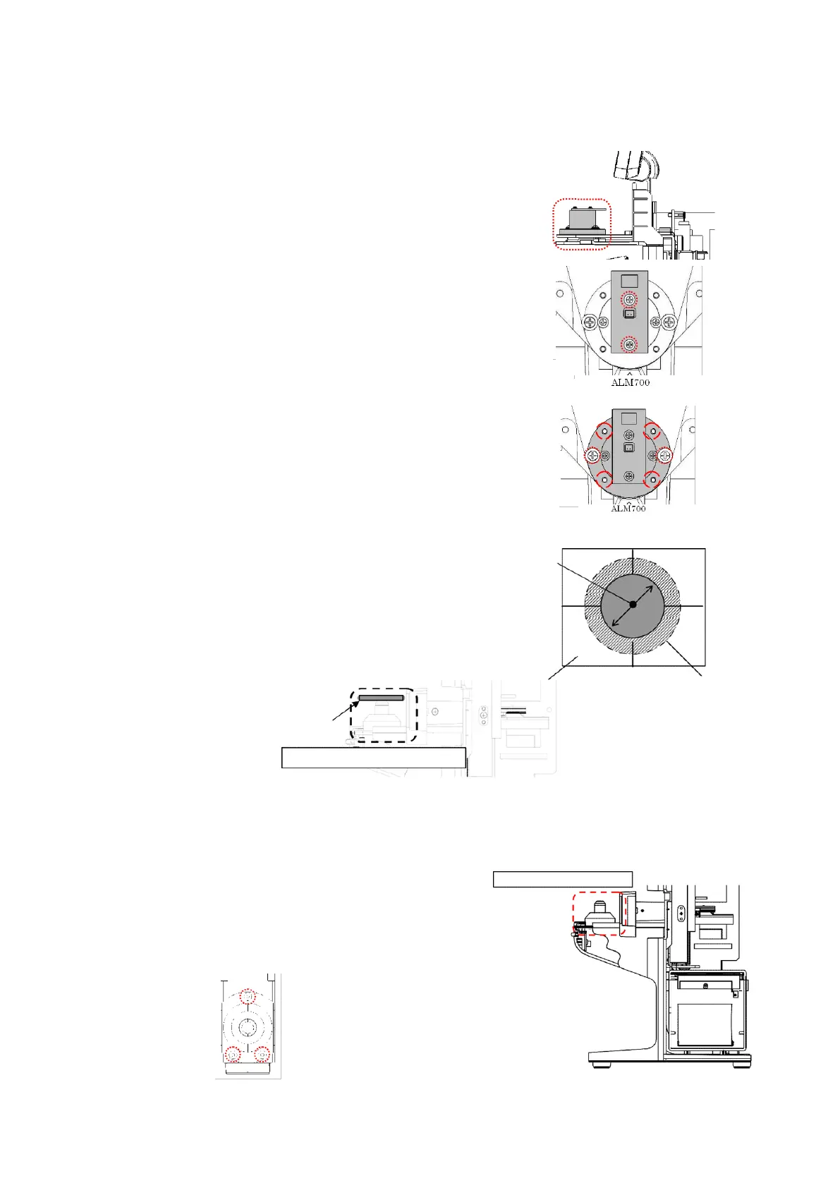
1) Replacement of Measurement Light Board Assy.
Unscrew 2 screws (cross-recessed bind screw M2×L6 black)
fixing the measurement light board Assy., and place the
replacement measurement light board Assy. roughly in the
center.
After that, place each cover and perform calibration.
(Refer to ‘8. Calibration’.)
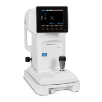
2) Replacement of Light Projecting Unit Assy.
Unscrew 2 screws (cross-recessed bind screw (P3) M3×10
black),
and place the replacement light projecting unit
Assy.
temporarily. :Fig. 2
Then, align with the optical axis of the light receiving
Assy. by using 4 M3 set screws.
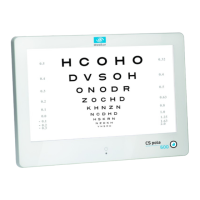
【Adjustment Criteria】
Place the perforated screen on the light receiving unit
Assy.
Confirm visually that the scribing line and light
from the light projecting unit match. :Fig. 3
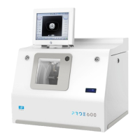
5.10. Light receiving unit assy.
Remove the light receiving unit cover.
(Refer to ‘4-4. Removal of Light Receiving Unit Cover’.)
Remove 3 screws (hexagonal socket cap low head bolt M3×6)
fixing the light receiving unit and harnesses connected, and
place the replacement light receiving unit Assy. roughly in
the center.
Light projecting unit assy.
Scribing line
ALM700: φ13
Light receiving unit assy.
Light receiving unit assy.