5.11. Marketing / Retention latch
Remove the back cover. (Refer to ‘4. Assembly and
Disassembly of External Facing’.)
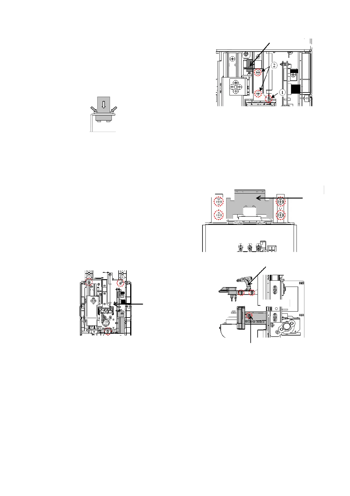
Remove the spring holding the marking/ retention unit Assy.
:①
Unscrew 2 screws (cross-recessed bind screw M3×5) fixing
the plate which the marking/ retention latch is mounted. :②
Hold both sides of the marking/ retention latch, and remove
it to the direction of arrow. :Fig. 2
[Fig.2]
5.12. Front cover
Remove the back cover, top cover and LCD Assy.
(Refer to ‘4. Assembly and Disassembly of External Facing’.)
Then, remove the LCD retention BKT by unscrewing 4
screws
(cross-recessed bind screw M4×6) fixing it. :Fig. 1
Remove the FGs screwed on measurement light board Assy.
(CN9), CMOS camera board (CN3) and mechanical unit
frame which are connected to the control board Assy. (Refer
to ‘3.Wiring Diagram’ ): Fig. 2
Remove the marking/ retention Assy. and PD plate. :Fig. 3
Replace the front cover by removing the mechanical unit,
terminal unit Assy., power supply switch, rubber legs and
bottom plate which are fixed on the front cover in order.
[Fig.3]
 Loading...