5.6. Power supply switch
Remove the back cover.
(Refer to ‘4. Assembly and Disassembly of External Facing’.)
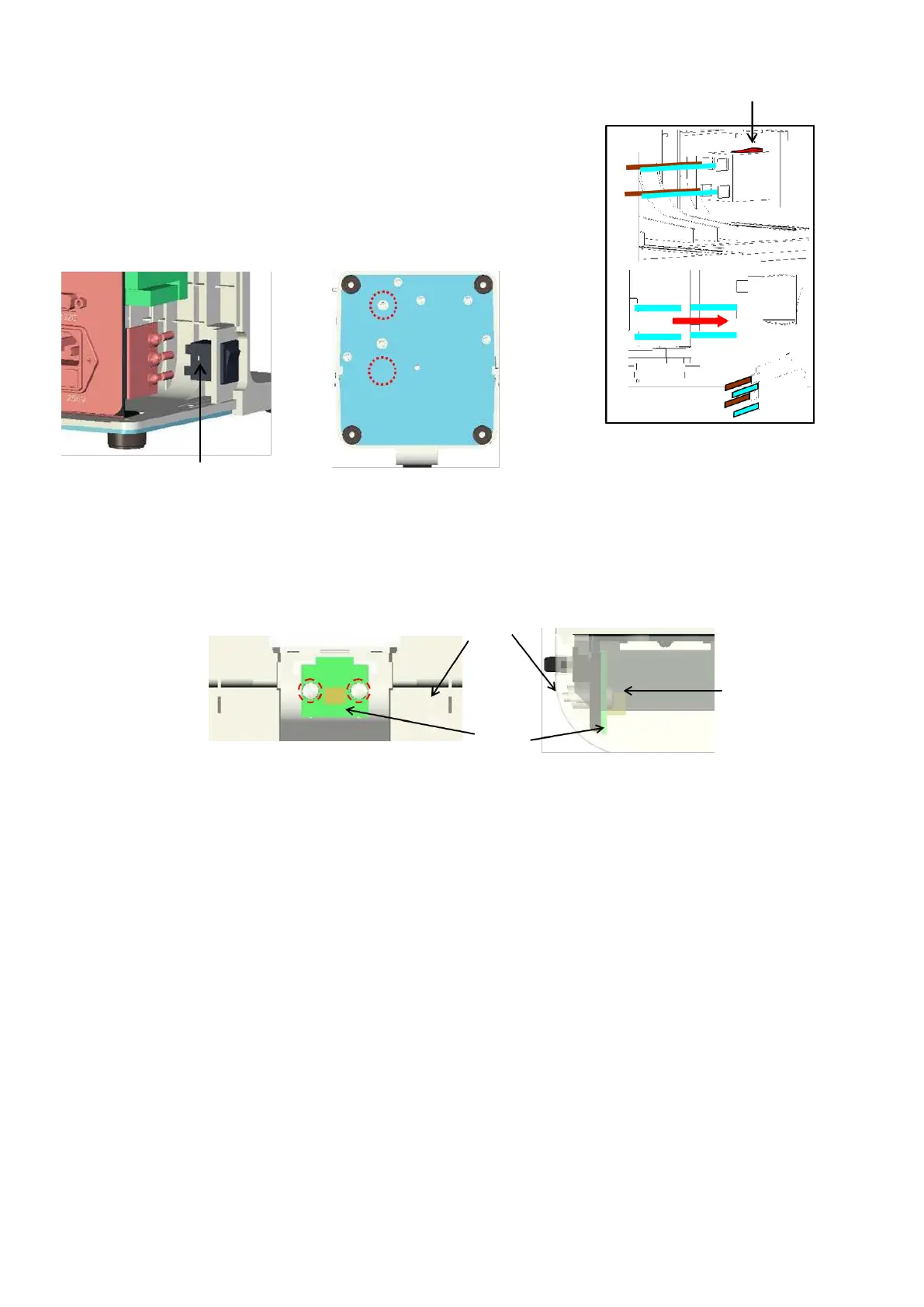
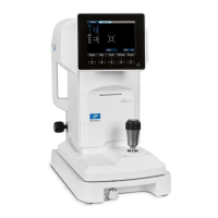
Remove the terminal unit Assy. by unscrewing 2 screws
(cross-
recessed bind screw M3×5) fixing the Assy.
(
※
Do
not disconnect the harnesses.): Fig. 1 and 2
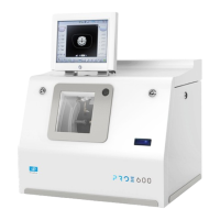
Remove the power supply switch by pressing the click. :Fig. 3
Replace the harnesses of the power supply switch and power
supply switch.
5.7. Memory switch board assy.
Remove the front cover in the manner of ‘5-13 Front Cover’.
Unscrew 2 crews (P tight 3×8) fixing the memory
switch board Assy