4.2. Removal of LCD assy
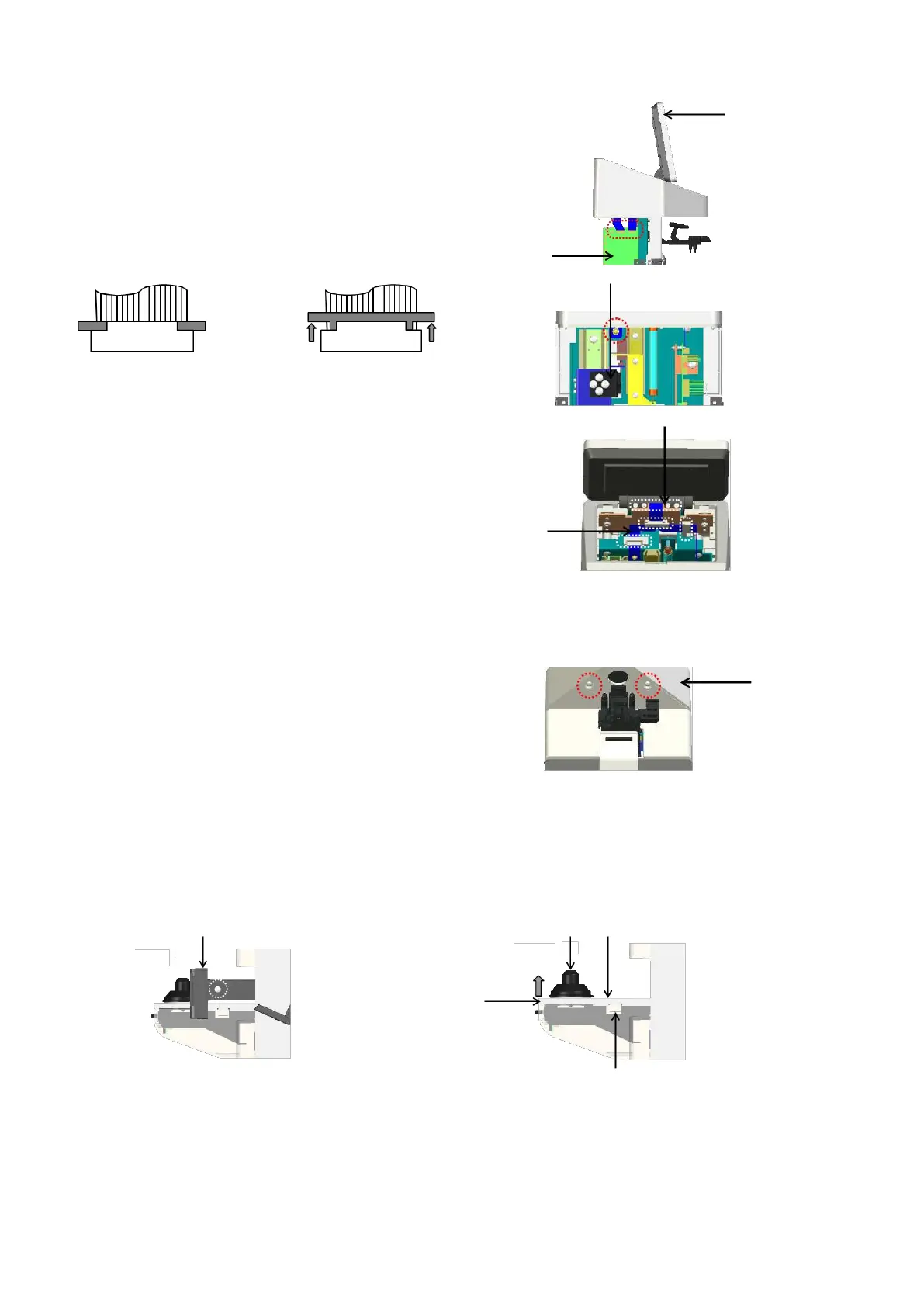
1) Remove 2 harnesses connected to the control board Assy.
from the LCD Assy. (CN4 and 5: flat cables): Fig. 1
*
CN5 has the lock function of the harness. Remove the
harness from the control board Assy. by unlocking it.
Unlocked
*
Move the lock units on both right
and left sides at the same time at
the time of unlocking them.
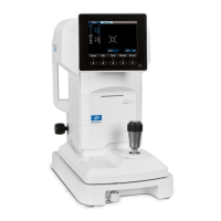
Unscrew the screw (cross-recessed pan head screw M3×8)
fixing the GND harness located behind the lens holder by
lowering the holder.: Fig. 2
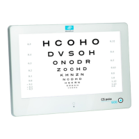
Remove the clip fixing the harness from the LCD Assy.: Fig. 3
2) Remove the LCD Assy. by unscrewing the screws (hexagon
socket cap low head bolt M3×6 black) fixing the LCD Assy.:
Fig. 3
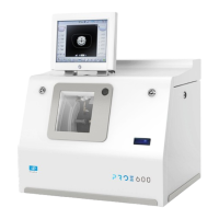
4.3. Removal of top cover
Remove the top cover by unscrewing 2 screws
(cross-recessed bind screw M3×8) fixing the top cover.: Fig. 4
4.4. Removal of light receiving unit cover
Remove the lens plate by unscrewing 2 screws (cross-recessed bind screw M3×8 black) on both sides of
right and left.: Fig. 5
Remove the lens holder. The light receiving unit cover is fixed with the click. It can be removed by
lifting A part of the cover.: Fig. 6
Light receiving unit
cover