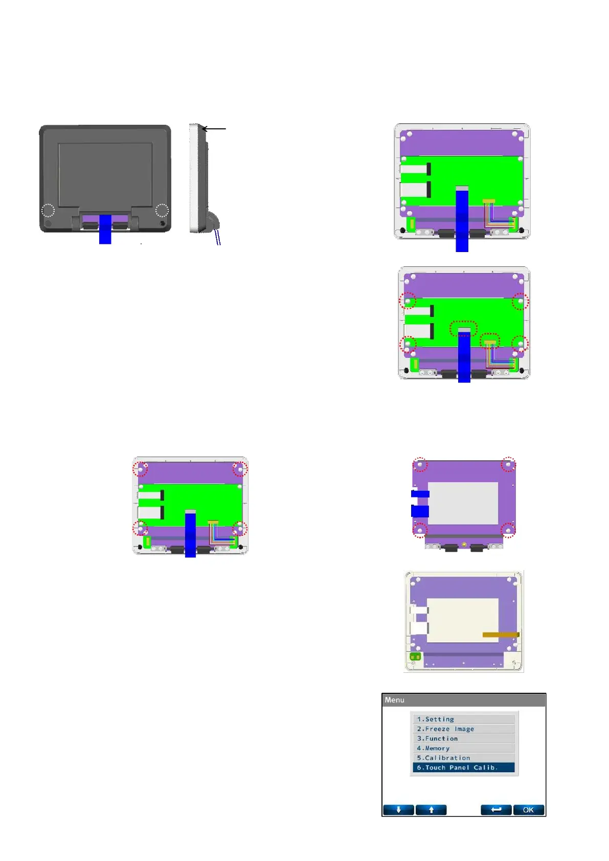
5.3. LCD assy.
Remove the LCD Assy. (Refer to ‘4-2 Removal of LCD Assy.)
Remove the LCD bottom cover by unscrewing the screws (cross-recessed bind head tapping screw 3×8) after
removing the screw hidings.
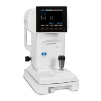
1) Replacement of LCD Relay Board Assy.
Disconnect the harness connected to the LCD relay board
Assy.
Replace it by unscrewing 4 screws (cross-recessed bind
screw M3×5 black) fixing the board.
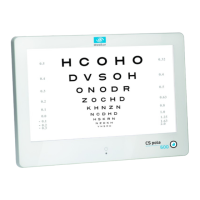
2) Replacement of LCD
Unscrew 4 screws (cross-recessed bind head tapping screw
3×10) fixing the LCD BKT. :Fig. 1
Replace it by unscrewing 4 screws (cross-recessed bind head
tapping screw 3×8) fixing the LCD. :Fig. 2
3) Replacement of LCD Top Cover/ Protection Plate/ LCD unit
(ALM700).
The LCD top cover, protection plate and operation switch
board Assy. cannot be replaced separately.
They can be only
replaced as a set.
Remove and replace the LCD BKT in the manner of 2).
In case of ALM700, LCD top cover/ protection plate/ operation
switch board Assy. cannot be replaced because it is touch
panel. It can be replaced as LCD unit.
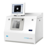
4) In case of replacing the LCD top cover/ protection plate (with
touch panel), it is necessary to adjust the touch panel.
The adjustment can be performed in ‘6. Touch Panel Calib.’ on
Menu in the dealer mode.