Copyright 2003-2013 CSM CO.,LTD
- 13 -
APC-TF Series
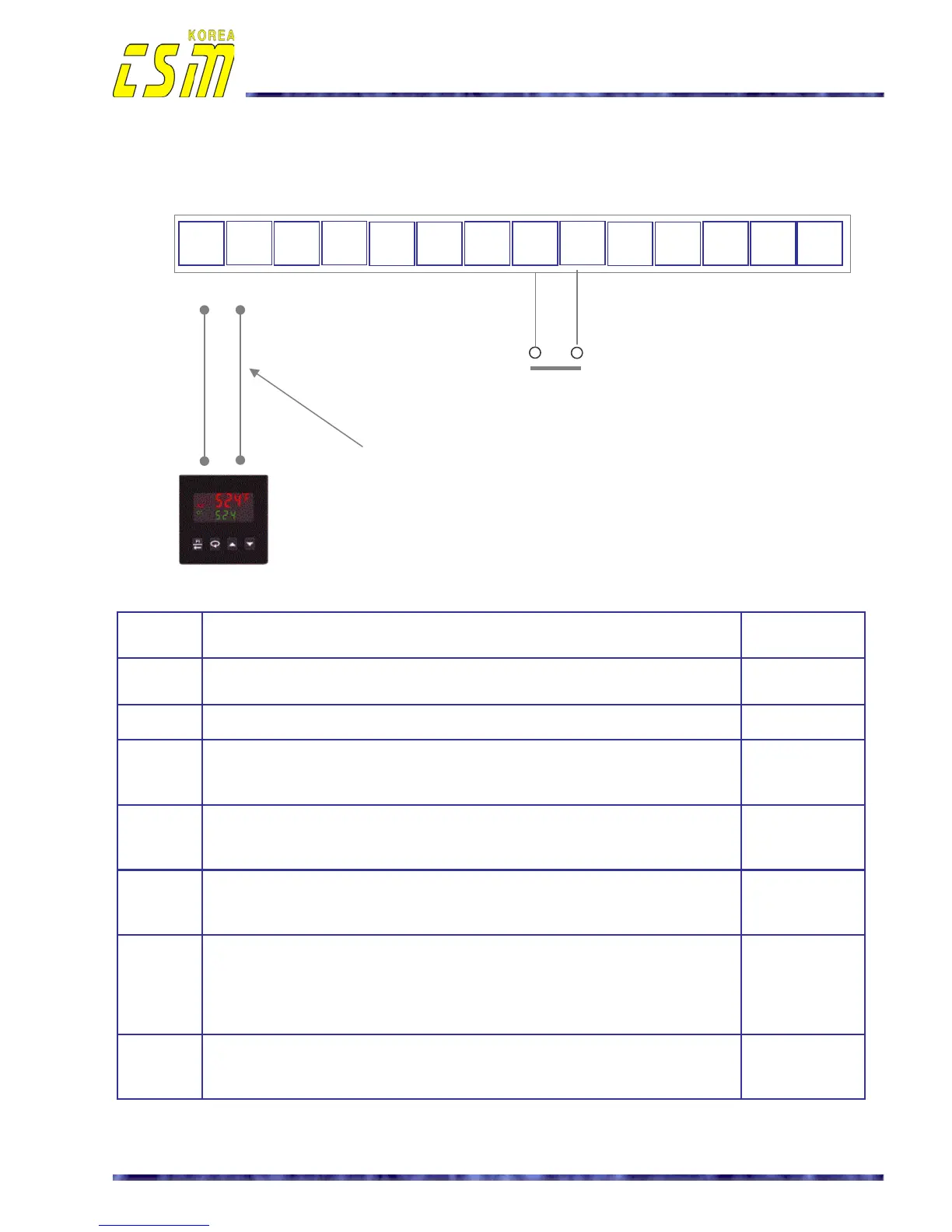
Automatic operation wiring diagrams
• Automatic operation mode :
External input wiring from TIC
①
②
③
④
⑤
⑥
⑦ ⑧
⑨
⑩
⑪
⑫ ⑬ ⑭
+ -
NC COM NO
+ -
State
items
The setting up items and explanation
Default
value
External
signal
The external signal must be connected to the control terminal block
between terminal 2 (‘+ Input’) and terminal 3 (‘0V’).
-
SW3 INT MODE : Internal potentio meter select INT MODE
SW4
AUTO MODE : Automatic operation mode select
The setting up in the case which the utility does an AUTO/MAN switch in the
outside control panel at necessarily select AUTO mode.
AUTO MODE
SW5
STOP MODE
** Use when the liver diagnoses or power controller test.
If select of “RUN” mode ,the control is impossible to an external of contact.
STOP MODE
S.S
The time set for soft start, stop, up, down control. (1-10 Sec)
The setting up of soft control value for start time, stop time, up time and
down time so that it is suitable to the characteristic of the load at 1-10 sec.
3 sec
P.W
It uses output voltage, current, conduction angle, phase-shift and power
factor to compute the power.
The adjustment range is 0 to 100% of the units rating.
The case of a guidance inductive load, order the increase adjustment
clockwise slowly from necessarily 0 % to maximum stability range.
100 %
O.C
Over current setting up.
Power controller set in “STOP” situation and set of the load capacity
in 120 – 150% range.
Nominal
current 115%
*
Signal, control cables :
Use the shield cable (CVVSB: more then 0.75mm
2
)
[NOTE]
CVVSB : PVC INSULATED, COPPER WIRE BRAID SHIELD AND
PVC SHEATHED CONTROL CABLE
OPEN : Stop
CLOSE : Running
TIC : Temperature indicate and controller
4 – 20mA
Potentio meter AUTO/MANUAL RUN/STOP Reset Alarm relay

 Loading...