E10 Operation Manual V1.15
3.5 Rear Panel
3.5.1 Rear panel
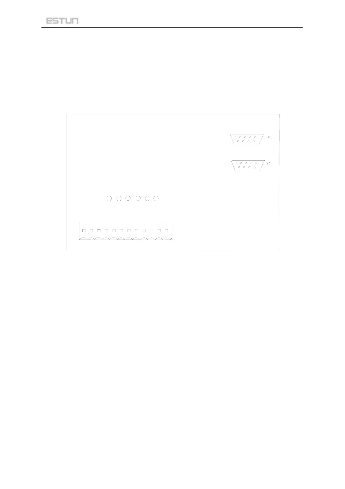
On the rear panel (Figure 3-1) , there are input instructions, output instructions, encoder interface and
connection port (wirings see appendix). The significance of the indicator light will make the following
introduction.
OUT4OUT3OUT2
OUT1IN2
IN1
OUT3
0V
+24V
GND
AC2
AC1
24V
IN1 IN2
OUT2
OUT4
OUT1
Figure 3-1 Rear Panel
3.5.2 Power supply
AC1 --------------------------- power supply of +24 V, or one end of AC power.
AC2 --------------------------- power supply of 0 V, or the other end of AC power.
GND -------------------------- GND.
+24 V -------------------------- 24 V.
3.5.3 Input and output signals
IN1 --------------------------- input channel 1 input (shears for shearing count input signal).
IN2 --------------------------- input channel 2 input.
OUT1 --------------------------- output channel 1 output.
OUT2 --------------------------- output channel 2 output.
OUT3 --------------------------- output channel 3 output.
OUT4 --------------------------- output channel 4 output.
0V --------------------------- common port of input and output channels.
24V --------------------------- common port of output channels.
Page 5 of 28