E10 Operation Manual V1.15
3.6.2 Debugging
1. You must check power and ground wire as well as other wiring is correct before power on.
2. Check if system is working properly, and power off immediately if not.
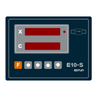
3. Check the digital interface, all digital tubes should be lit in this time.
4. Enter the interface of the machine parameters, set the machine parameters, then enter the teach in
parameters interface, set the parameters of teach in, check digital tube display if the value is correct.
5. Check the input signals.
6. Check the output signals.
7. Measure a machine screw gap through the following simple method.
X-axis is expected to specify as an example.
Firstly, confirm the screw gap parameter of X-axis is set as‘0’.
Secondly, make X-axis to walk away at least two screw-pitches in the increasing direction to the
location of ‘100.0’, then measure the actual location of X-axis, write it down as X1;
Thirdly, make X-axis to walk away at least two screw-pitches in the decreasing direction to the
location of ‘100.0’, then measure the actual location of X-axis, write it down as X2.
And the value of (X2-X1) is actual screw gap value of X-axis.
Enter the X-axis screw gap value to PAN07 (bending machine) PAN04 (shearing machine).
Measuring for Y-axis is the same as X-axis, and input the value to the PAN08 (only bending
machine).
When moving is not one-way positioning manner, the alarm indicator light will be lit.
The alarm shows a one-way positioning must be made.
Make X-axis to walk away some distance (at least greater than the transmission gap) in the increasing
direction, and then make X-axis to walk away in the decreasing direction to the origin location, and the
alarm indicator light goes out.
3.6.3 Actual processing
When all the above steps complete, teach in X, Y axis as the actual location.
Do actual processing, measure the finished work-piece, and then adjust the error correction if there is
difference.
Note:
1. It is necessary to observe closely whether the motor is running normal.
2. Power off if emergent.
3. Determine whether a output has output by the corresponding indicator light on the rear panel.
Page 7 of 28

 Loading...