12 Lonestar User Manual
DMX Control
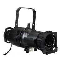
The Lonestar fixture operates on standard DMX-512 control bus, controlled by a DMX console.
The fixture requires 48 channels of DMX-512.
Attach the fixture to the control bus using a two-core, shielded cable with a 5-pin XLR connector
(Belden 9729 is preferred).
The fixture includes two 5-pin XLR connectors, one for DMX In and one for DMX Thru (for use
when daisy-chaining fixtures on the DMX control bus). (See
Fixture Overview on page 6
.)
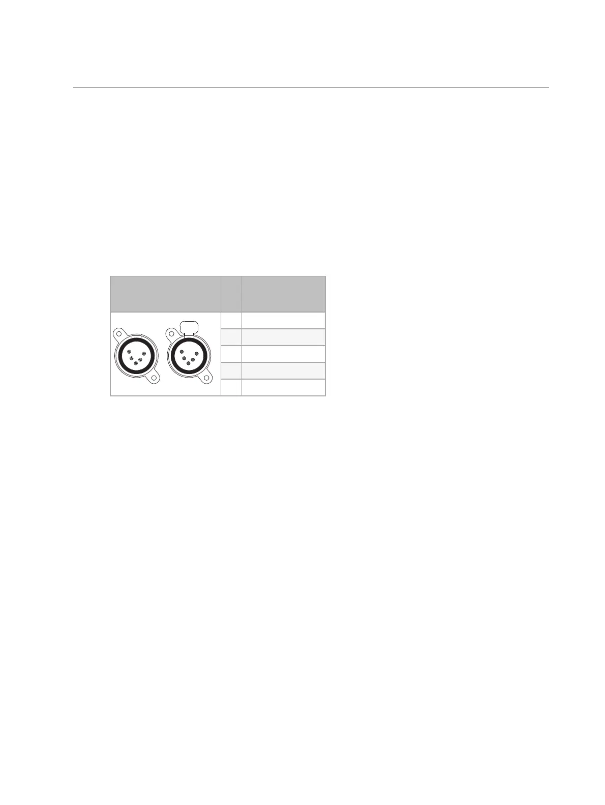
DMX Connector Pinout
Use the following standard pinout when preparing DMX cable with 5-pin XLR connectors. ETC
recommends using Belden 9729 or equivalent cable. (See the ETC cable cross database for
equivalent alternatives: etcconnect.com/Support/Cable-Cross-Database.aspx.) The second data
pair in the recommended cable type is not used, but is reserved future service.
DMX-512 Pinout
for five-pin XLR
Pin Use
1 Common (shield)
2 Data -
3 Data +
4 not connected
5 not connected
Connect DMXCables to Fixture
The following instructions are guidelines for connecting DMX to your fixture. Your installation
may vary.
1. Connect a DMX data cable to the DMX control source and the DMX In XLR receptacle on the
first fixture in the DMX data run.


 To Next Page