10 CEM+ Sensor Rack Retrofit Manual
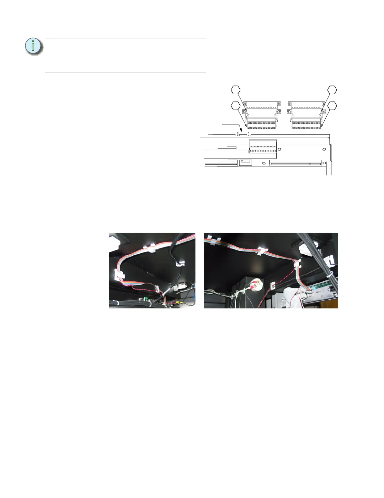
Step 9: Install the dimmer output
ribbon cables/transition
cards. The order/layout is
not the same as on the old
backplane. See the
illustration below. Make
sure the proper side is
facing up on each
connector and that each
connector is fully seated.
Step 10: Plug the control input ribbon
cable into the header on the
backplane. The connector
is keyed - the ribbon cable
will go up.
Step 11: Plug the 2' Ethernet cable into the RJ45 connector on the backplane.
Step 12: Dress the control data ribbon cable, the beacon cable and the Ethernet cable
neatly across the top of the rack. The cables should be supported every 6” to 8”
from the control input panel to the backplane. Use the provided ribbon cable
mounts (ETC Part# HW726) as needed.
Note:
You cannot use the old screws
without the additional shoulder-
sleeve as they will block the
CEM+ from being fully inserted.
CEM+ Ribbon Cable Layout
(1-24)
(73-96)
(49-72)
(25-48)
1
2
3
4
Control data
ribbon cable
header
Cable routing on the input panel side Cable routing on the CEM+ side
 Loading...