6 CEM+ Sensor Rack Retrofit Manual
backplane metal. This connector will be used in the upgrade.
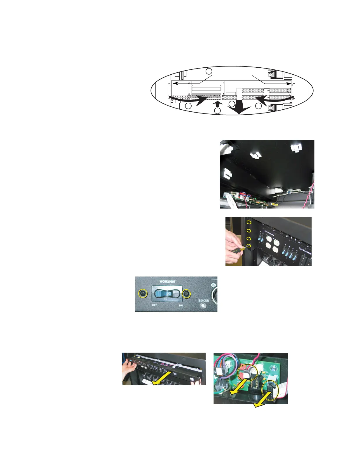
Step 6: Unscrew the backplane metal from the rack. (One screw in each side upper-
corner - two screws total.) Discard these screws. Replacement screws with
thread locker are provided (ETC Part# HW377).
Step 7: Push the backplane towards the back of the rack to free the backplane side tabs
Step 8: Bend the sides into the center (out of the sides of the rack).
Step 9: Slide backplane metal forward in order to
allow easier working space while
removing data terminations.
Step 10: Finish removing the old backplane
metalwork. Discard the old backplane.
Control Input Panel Replacement
Step 1: From the open left side of the rack,
remove the control data ribbon cable from
the clips inside the rack.
Step 2: Remove the tour guides on the rear of the
rack by loosening (not removing) the
three screws behind each tour guide.
Once the screws are loose, slide the tour
guide toward the center of the rack to
remove it.
Step 3: Remove the two screws that hold in the
breaker on the left side of the control
panel.
Step 4: Remove the screw on each side of the old control input panel.
Step 5: Pull the control input panel out a couple inches.
a: Unplug the beacon connector (twisted red & black wire).
b: Completely pull the panel out of the rack.
1 2 3 4 5 6 7 8 9
10 11 12 13 14
6
8 8
9
7
Remove the
backplane screws
R
e
mo
v
e
Re
m
o
v
e
D
i
s
c
a
r
d
 Loading...