Do you have a question about the ETC Echo and is the answer not in the manual?
Specifies acceptable operating conditions: 0-50°C and 5-95% non-condensing humidity.
Outlines general installation procedures, electrical code compliance, and wiring practices.
Assigns space and unique station addresses using rear panel rotary switches.
Details the purpose of each DIP switch for station functionality, LED control, and defaults.
The ETC Echo Inspire Station is a versatile control device designed for use with Echo and Sensor control systems, offering comprehensive control over lighting presets, zones, space combinations, and color. This installation guide provides essential information for setting up and configuring the Inspire Station, ensuring proper functionality and integration within your lighting control environment.
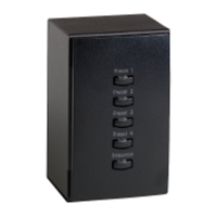
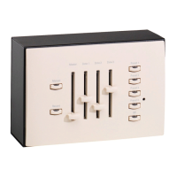
Inspire Stations are available in various configurations, including 1, 2, 4, 6, and 8-button assemblies, as well as a specialized 4-button with fader station. Each button on the station is equipped with both blue and amber LED backlighting, providing clear visual feedback. The fader knob on the 4-button with fader station is also backlit with a blue LED, enhancing visibility and usability in various lighting conditions.
The installation process for the Inspire Station involves several key steps, starting with preparing the installation site. Inspire Stations are shipped with the station electronics, a decorator-style wall plate, a termination kit, and a template for standard button labels. Users have the flexibility to install the station into an industry-standard back box (provided by others) or a surface-mounted back box (available separately from ETC).
Connectivity is established via the EchoConnect station communication bus, a bi-directional protocol that utilizes a single pair of wires for both data and power. ETC recommends using Belden 8471 Class 2 wire or an approved equivalent for EchoConnect wiring. The total combined length of an EchoConnect wire run using Belden 8471 should not exceed 500 meters (1,640 feet), with a maximum distance of 400 meters (1,312 feet) between any two devices. It is crucial that all control wiring is installed and terminated by a qualified installer, adhering to standard wiring installation practices. Approximately 25.4 cm (10 inches) of wiring should be left in the back box for connection and future service needs. For ESD protection, ETC mandates that all stations and devices be grounded. An additional 2.5 mm² (14 AWG) wire should be pulled for grounding if control wires are not installed in grounded metal conduit.
Environmental considerations for the Inspire Station include indoor installation only, with an operating temperature range of 0–50°C (32–122°F) and non-condensing humidity of 5–95%. Installation must comply with all local codes and standard electrical practices, particularly NEC Class 2 product wiring in accordance with NEC Article 725 and local jurisdiction requirements. The back box should be installed plumb and square, free of obstructions, and with all wiring correctly installed. The termination kit provided with Inspire Stations includes a power pigtail, a ground wire pigtail, spacers, and all necessary wire termination connectors.
When using Category 5 (or equivalent) cable on the EchoConnect communication bus, specific guidelines must be followed. Cat5 wiring requires termination using the EchoConnect Cat5 Termination Kit and must be installed using a bus topology. Users should refer to the installation guide provided with the Cat5 Termination Kit (7186A1207) for detailed termination instructions. It is important to note that not all topologies are supported with Cat5, necessitating careful planning to ensure appropriate termination kits are available and the wire is pulled correctly.
Connecting the wiring involves pulling all required data wires (data+, data-) into the back box. If the station is not installed in grounded metal conduit, an additional ESD ground wire is required. The station ESD ground wire pigtail, provided in the termination kit, should be connected by stripping 11 mm (7/16 inch) of insulation from its ends and the incoming ground wire. A WAGO connector, also from the termination kit, is used to connect these wires. For stations using grounded metal conduit, the ground pigtail connects to the metal back box ground location. Finally, the ESD ground wire pigtail FASTON connector is installed into the mating receptacle on the station electronics.
Terminating EchoConnect wires is straightforward as EchoConnect is topology-free, allowing installation in any combination of bus, star, loop, or home-run. Users should strip 11 mm (7/16 inch) from the ends of each power pigtail wire (from the termination kit) and the installed control wires. WAGO connectors are used to connect the power pigtail wires and the Belden 8471 control wires, with one WAGO for the white wire pair (data +) and one for the black wire pair (data -). The terminal levers on the WAGO connector are opened, the wires inserted, and the levers closed. The two-pin connector from the power pigtail is then installed into the mating receptacle on the station electronics.
The Inspire Station features rotary and DIP switches for configuration, accessible on the rear of the station. Two rotary switches are used for space assignment and station address assignment, with each station requiring a unique address within its assigned space. By default, these switches are set to Space 1, Station Address 1. DIP switches provide additional functionality, including "Off" functionality, disabling amber button LEDs, 4-button station space combine controls, 4-button with fader station color control mode settings, and restoring factory defaults.
DIP switch settings include:
When the station Function switch is set to Custom, only DIP switch number 8 applies, and all other DIP switch settings are ignored. For detailed information on the Function selection switch, users should consult the Echo Inspire Station Programming Guide, available for download from etcconnect.com.
For 4-button with fader stations, DIP switches 5 and 6 control Color Mode functionality for the fader knob when the station is also set to Zone control mode.
The Inspire Station also features on-board switch and button settings accessible from the front of the station once the cover is removed. The Echo Inspire Station Programming Guide provides information on local settings, including configuration, program and record mode, and station functionality. ETC user documentation is available on etcconnect.com, and the EchoAccess Mobile App integrated help system offers details on custom configuration using EchoAccess. To configure the Inspire Station using EchoAccess, the station Function switch must be set to Custom.
Maintenance features include installing button legends. Inspire Stations ship with standard button legends installed beneath a clear lens, and an additional sheet of standard legends is provided for field installation. Users can also customize and print their own button legends on standard transparency using a template downloaded from etcconnect.com. To remove, install, or replace a button legend, the bezel and button lens must first be removed from the station electronics. The bezel has notches at each corner for easy removal. The button lens is removed by pressing and sliding it towards the button hinge points. Once the lens is off, the existing legend can be replaced. Reattaching the lens involves aligning its grooves with the button, sliding it into place from the hinge until it covers the entire button and clicks. Finally, the bezel is replaced.
Installing the station into the back box involves using receptacle spacers to align the station and cover flush against the wall in flush-mount applications. Spacers are not needed for surface-mount back boxes. The station electronics and wiring are inserted into the back box. For multi-gang installations, insert station electronics from right to left for optimal alignment, as the alignment bracket will slightly overlap the station to the right. Spacers can be folded in a zig-zag fashion to achieve the necessary thickness to fill the gap between the station, wall surface, and back box, with any excess cut off. The stack of spacers is placed between the station electronics and the flush-mounted back box. Each station electronics unit is secured with two screws, inserted through the spacers if used. It is crucial not to overtighten the screws, as this can negatively impact button activation.
Finally, installing the wall plate is facilitated by built-in magnets. The top of the wall plate is aligned with the station at approximately a 20-degree angle. The top of the wall plate hooks onto tabs on the station electronics assembly; wiggling it slightly side to side ensures proper engagement. The bottom of the wall plate is then swung down until the magnets engage. If the wall plate does not fully attach, wiggling the bottom of the plate helps ensure all magnets are properly seated and the plate is secure. For multi-gang wall plates, if stations are misaligned in the back box, the wall plate will not attach correctly. In such cases, the screws securing the stations to the back box should be loosened, stations adjusted for better alignment, screws re-secured, and the wall plate reinstalled.
| Category | Control Systems |
|---|---|
| Outputs | DMX |
| Network | Ethernet |
| Weight | Varies by model |
| Type | Lighting Control |
| Communication Protocol | sACN |
| Operating Temperature | 0°–40° C (32°–104° F) |
| Storage Temperature | -20°–70° C (-4°–158° F) |
| Enclosure | Plastic |
| Connectors | RJ45, DMX |