2 The Retrofit 7
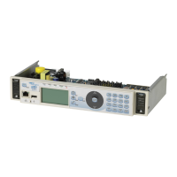
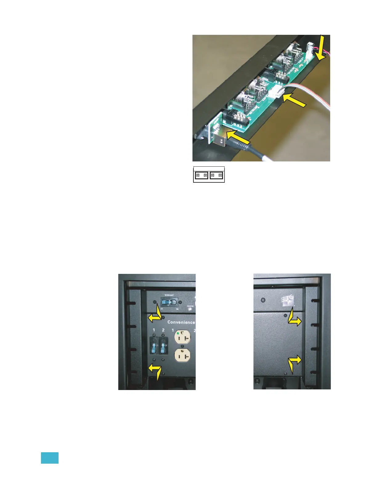
Step 6: Connect the data cables
to the new control input
panel.
a: Insert the Ethernet
cable in the RJ45 jack
on the rear of the
control input panel.
b: Connect the new
control data ribbon
cable connector (the
connector is keyed - the
ribbon cable will go up)
in the new control input
panel ribbon cable
header. Both ends of
the control data
ribbon cable are the
same.
c: Connect the beacon
connector to either the
first or last pair of the
beacon header (show
here).
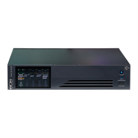
Step 7: Feed the cables into the rack where the control input panel will go and reinstall
the breaker with the same two screws. Be sure to note the proper on/off
orientation of the breaker to the panel labeling (The new panel and the old
panel are the same).
Step 8: Install the new control input panel in the rack. Leave the screw on each end of
the panel a bit loose for the next step.
Step 9: Reinstall the tour guides (under the screw heads still in the rack) and fully tighten
the screws for each side.
Co
n
n
e
c
t
C
o
nn
e
c
t
C
o
n
n
e
c
t
Use either pair
 Loading...