24 DSCDP Hardware Manual
ETEL Doc. - Hardware Manual # DSCDP / Ver G / 6/1/11
The D-Sub 15 pins high-density connector is only available on the DSCDP3xx-xxx.
Remark:
The +5VDC encoder supply output is protected by the fuse F3 (1A) on JC5 and JC6.
Refer to the corresponding ’Operation & Software Manual’ for more information about the use
of the EHO and ELS signals.
JC5 is used to connect the encoder of motor 1 and JC6 for the one of motor 2.
3.1.1.2 Absolute analog encoder (EnDat 2.1)
The EnDat 2.1 is an absolute encoder. It has 1Vptp signals with a load resistor R
0
=120Ω. Its signals are
similar to the incremental encoders (without the index), but it additionally includes a RS485 serial link (EIA
standard, EnDat 2.1 interface) for the absolute position measure: EDT (serial data) and ECL (clock). The ECL
(clock) signal is received from the DSCDP. From its first falling edge (latch signal), the absolute position will
be defined within one incremental signal period (depends on the encoder type).
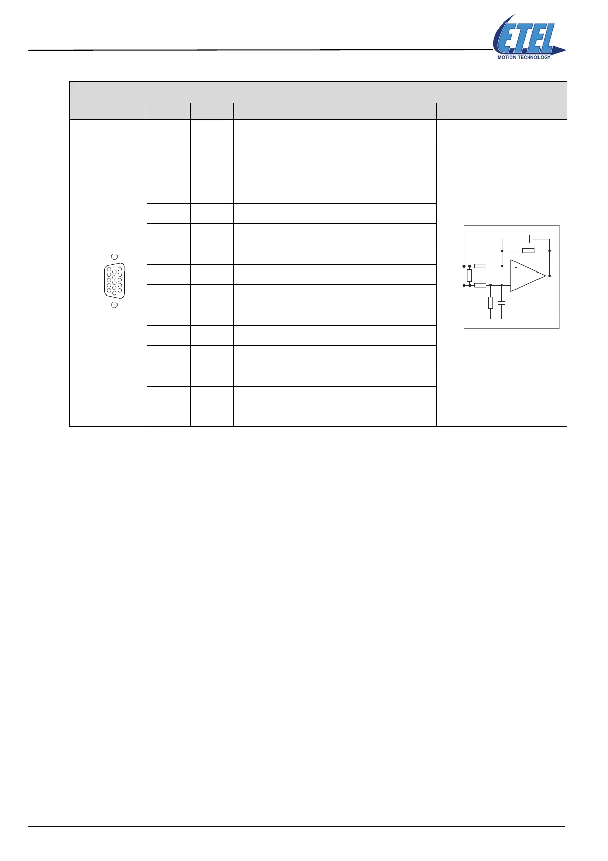
The D-Sub 15 pins high-density connector is only available on the DSCDP3xx-xxx.
D-SUB, 15 pins, high density, female
ANALOG ENCODER Pin # Signal Function Interface
1Reserved
Do not connect
2Reserved
Do not connect
3Reserved
Do not connect
4+5VDC
Encoder supply output (protected by fuse F3 of 1A)
5GND
Encoder supply output (0V)
6COS -
Cosine - signal input
7 SIN -
Sine - signal input
8IDX -
Index - signal input
9Reserved
Do not connect
10 EHO
Encoder home switch input (TTL signal)
11 ELS
Encoder limit switch input (TTL signal)
12 GND
Encoder supply output (0V)
13 COS +
Cosine + signal input
14 SIN +
Sine + signal input
15 IDX +
Index + signal input
ANALOG ENCODER
1
5
15
11
JC5 & JC6
COS +
SIN +
IDX +
COS -
SIN -
IDX -
R
R
R0
C
C
DSCDP
Artisan Technology Group - Quality Instrumentation ... Guaranteed | (888) 88-SOURCE | www.artisantg.com
 Loading...
