ETEL Doc.- Hardware Manual # DSCDP / Ver G / 6/1/11
DSCDP Hardware Manual 25
Remark: The +5VDC encoder supply output is protected by the fuse F3 (1A) on JC5 and JC6.
The cable used with an absolute analog encoder (EnDat 2.1) must have power wires with a
minimum diameter to guarantee a sufficient voltage at the terminals of the encoder (refer to the
data sheet of the encoder for more information).
JC5 is used to connect the encoder of motor 1 and JC6 for the one of motor 2.
3.1.1.3 TTL encoder
Caution: It is possible to connect a TTL encoder on this connector but the input frequency is limited
to 400KHz because the interface is an analog one.
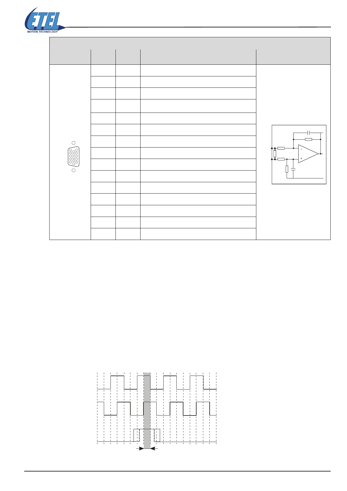
TTL encoders measure the motor position with 2 phase-shifted TTL signals. Each change of state of one of the
signals corresponds to an increment of the motor position. A third signal (index) gives the motor absolute
position. The encoder TTL signals have to be compatible with the EIA standard RS422. These signals have
the following form:
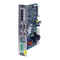
D-SUB, 15 pins, high density, female
ANALOG
ENCODER
Pin # Signal Function Interface
1EDT +
EnDat serial data I/O + / RS485
2ECL +
EnDat clock output + / RS485
3ECL -
EnDat clock output - / RS485
4+5VDC
Encoder supply output (protected by fuse F3 of 1A)
5GND
Encoder supply output (0V)
6COS -
Cosine - signal input
7 SIN -
Sine - signal input
8Reserved
Do not connect
9EDT -
EnDat serial data I/O - / RS485
10 Reserved
Do not connect
11 Reserved
Do not connect
12 GND
Encoder supply output (0V)
13 COS +
Cosine + signal input
14 SIN +
Sine + signal input
15 Reserved
Do not connect
ANALOG ENCODER
1
5
15
11
JC5 & JC6
COS +
SIN +
COS -
SIN -
R
R
R0
C
C
DSCDP
Signal TTL1 (UA1)
Signal TTL2 (UA2)
Index TTL0 (UA0)
Reference mark acquisition zone
Artisan Technology Group - Quality Instrumentation ... Guaranteed | (888) 88-SOURCE | www.artisantg.com
 Loading...
