7
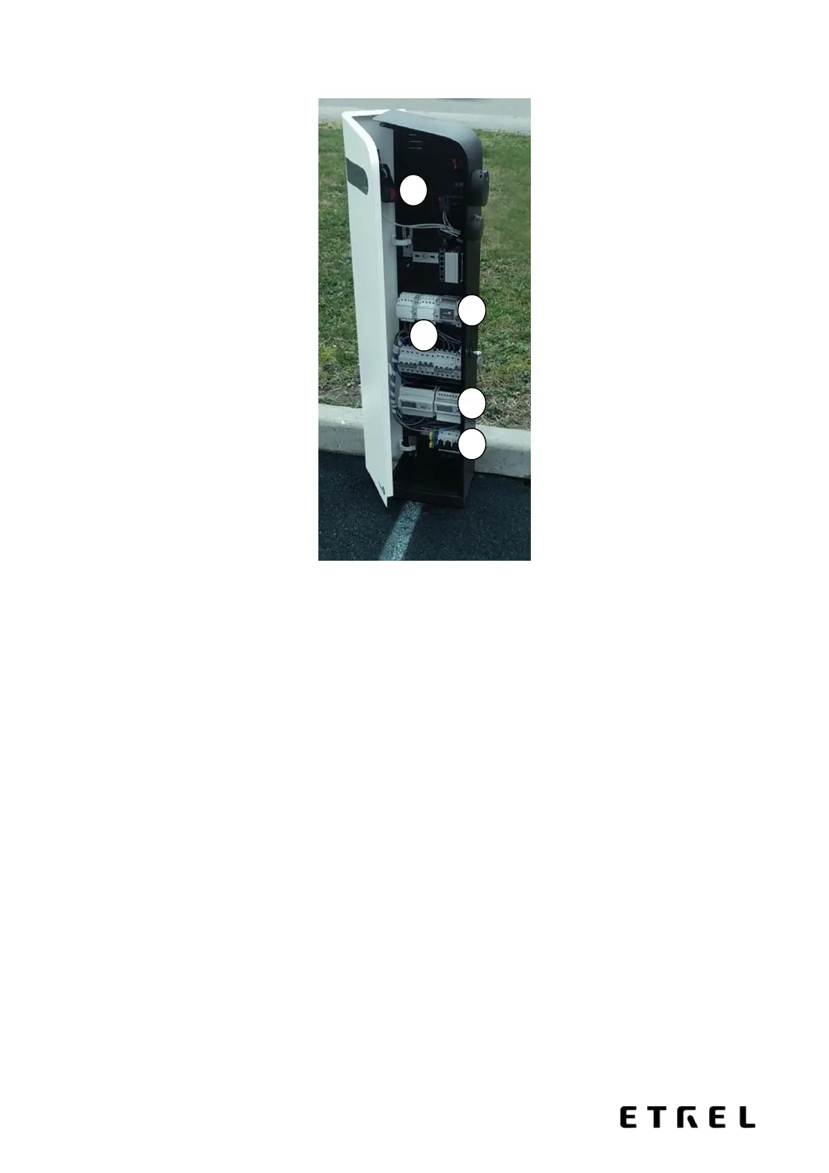
Figure 2: Arrangement of equipment inside the station
The figure above shows the general arrangement of equipment inside the charging station. The
station comprises several different functional units:
1. Grid connection module of the charging station, which contains terminals for all supply
wires (L1, L2, L3, PE, N);
2. Energy meters for each socket. For normal functioning of the station, a working
communication connection between the main station controller and the energy meters
is required;
3. Differential and overcurrent protection of each socket;
4. Module for communication with electric vehicle (compliant with the IEC 61851
standard), socket voltage monitoring components, socket contactors;
5. Main station controller with RFID reader, RFID antenna and LCD display, control circuit
power supply, and communication modules (Ethernet or GPRS router).