Assembly and Installation | 25
13. When mounting to a steel pit and steel raised floor, a #7 drill bit for
tapping or a 9/32 drill bit to create through holes is required when
mounting anchor plates to the steel raised floor. Locate and mark holes
in each group of anchor plates. Drill and tap or drill through each hole
and then screw in 1/4–20 hardware so that the turntable does not move
as you go around each location.
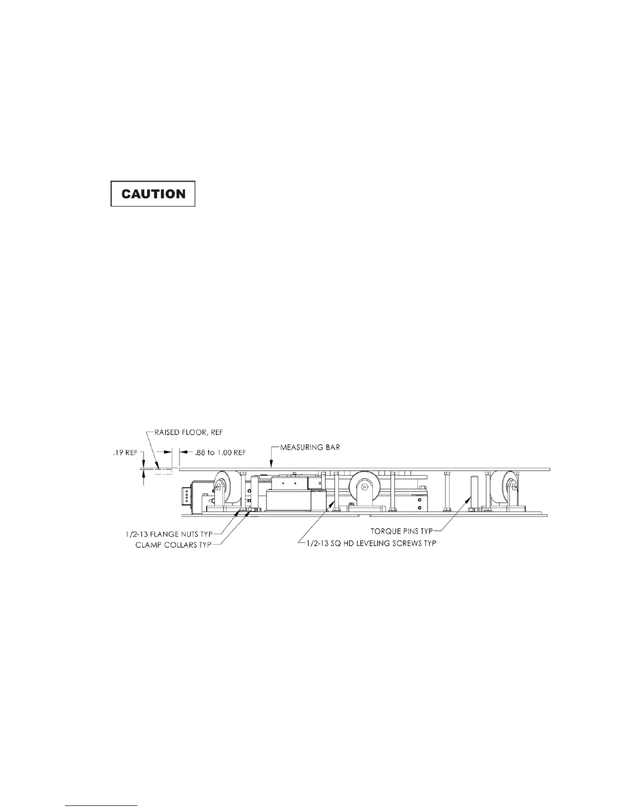
Before leveling, make sure all 1/2–13 flange nuts and clamp
collars are backed off completely to avoid pulling plates off the
floor.
14. Raise the turntable by turning the 1/2–13 square head screws clockwise
until the measuring bar top is 3/16 in above the raised floor; this is just a
rough finished height. Check the height with a leveling instrument.
When the turntable is leveled, tighten flange nuts on the square head
screws and secure set collars on the torque pins down onto the base top
surface and outer plate, if applicable. Remove the measuring bar. See
the Elevation View illustration in the next section and the drawings
located in the back pocket of this manual.
FLOOR FLANGE INSTALLATION IN A PANELED FLOOR
Elevation View
The ground ring assembly includes a floor flange with a mounted brush ring that
interfaces with the contact ring mounted beneath the turntable top. The floor
flange provides constant electrical contact with the ground plane.
Mounting methods vary according to user specifications. Clearance holes are
provided at evenly-spaced intervals along the outside perimeter of the
floor flange to attach to a customer supplied ground plane. These instructions
describe installation for a paneled floor. For concrete pit mounting instructions
see Floor Flange Installation in Concrete Pit on page 26.