Eubank EAA/EGA Wall Mount AC Installation & Operation Manual
03/2021 Rev.5
23
Power
The Marvair PCB requires 24 VAC to operate. When the board is sufciently powered, the “PWR”
status light on the PCB illuminates “Green.” If there is insufcient power to the board, the “STATUS
1” and “STATUS 2” ashes continuously. Insufcient power to the board will result in no outputs being
energized.
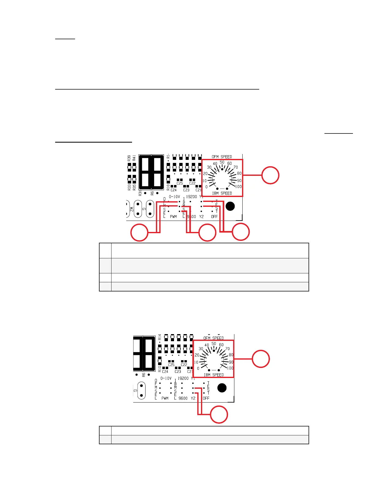
Setting the Speed for the Y1 and Y2 Operation for Indoor Motor
Put Bridge Jumper between the “Y1 pin and center pin” shown in the gure below. Use the potentiometer
marked “IBM SPEED” to set the required speed for rst stage cooling (Y1 request). Note that the type
of control signal required by the motor must be set and the appropriate signal terminations must be used.
This jumper will be factory installed. In replacing the PCB, verify the necessary signal and congure
the board accordingly. Only 2 of the 3 pins should be used for the necessary congurations. DO NOT
CONNECT ALL 3 PINS.
4
1 2
3
1
Set for 0-10V Signal.
Jumper To Remain On The Appropriate Terminal For Correct Operation
2
Set For PWM Signal.
Jumper To Remain On The Appropriate Terminal For Correct Operation
3 Bridge Jumper Position for Setting Y1 Speed
4 IBM SPEED Potentiometer
Figure 6a. Setting the Speed for the Y1 and Y2 Operation for Indoor Motor
To set second stage cooling (Y2 request) speed, put Bridge Jumper on the “Y2 pin and center pin”
shown in the gure below. Use the potentiometer marked “IBM SPEED” to set the required speed.
2
1
1 Bridge Jumper Position For Setting Y2 Speed
2 IBM SPEED Potentiometer
Figure 6b. Second Stage Cooling Speed