Eubank EAA/EGA Wall Mount AC Installation & Operation Manual
03/2021 Rev.5
37
3.6 Bracket Installation
1. All models have built-in mounting anges.
2. Apply a bead of silicone sealer on the wall side of the bottom support brackets on the unit. Circle
the mounting holes with the silicone bead.
3. Refer to Figure 4. Attach the bottom support bracket to the wall using appropriate 3/8" diameter
hardware.
For example, on wooden structures, use 3/8" x 2-1/2" all-thread lag screws. The screws must penetrate
the center of the wall stud. Drill a pilot hole in the stud to prevent it from splitting.
3.7 Mounting The Unit
1. For wiring into the back of unit, locate the lower of the two knockouts on the wall side of the unit.
Drill a one inch hole in the shelter wall to match this opening. Allow sufcient clearance to run
3/4" conduit through the hole and to the unit.
2. Using an appropriate and safe lifting device, set the unit on the bottom support bracket mounted
on the wall. You must stabilize the unit on the bracket with the lifting device or by some other
means - the bracket alone is not sufcient.
3. Make sure that the duct anges are properly aligned with the wall opening. Adjust as necessary.
4. Note the holes in each side ange. Using the holes for guides, drill holes through the wall with a
3/8" drill bit. Insert the 3/8" x 5" bolts through the anges. Install nuts and washers on the inside
of the shelter. Tighten the bolts to secure the unit.
5. Apply a bead of silicone where the mounting ange contacts the unit and the shelter wall.
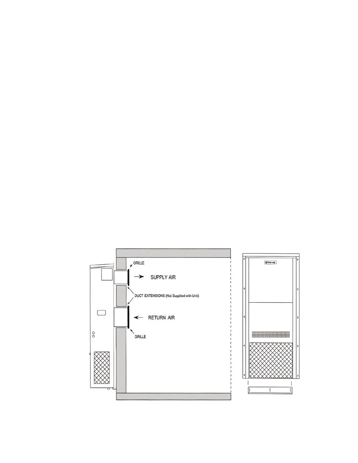
6. On the inside of the shelter, install the wall sleeves in the supply and return air openings. The sleeves
may be trimmed to t ush with the inside wall.
7. Check the t of each sleeve to its mating ange for possible air leaks. Apply silicone sealer to close
any gaps. Install the air return and supply grilles.
For units with electric heat, a one inch clearance is required around the duct extensions. The duct
extensions must be constructed of galvanized steel with a minimum thickness of .019” as per the
NFPA standards 90A & 90B.
Figure 12. Eubank A/C Wall Mount Detail