BitsyXb - User Manual
14 110118-0001A
3.2.1 JP2: LCD Display Power Select
Type: 3-post header, 2mm
This jumper selects the supply voltage for the LCD display. The three-pin header is located on the
corner of the board near the PCMCIA ejector button.
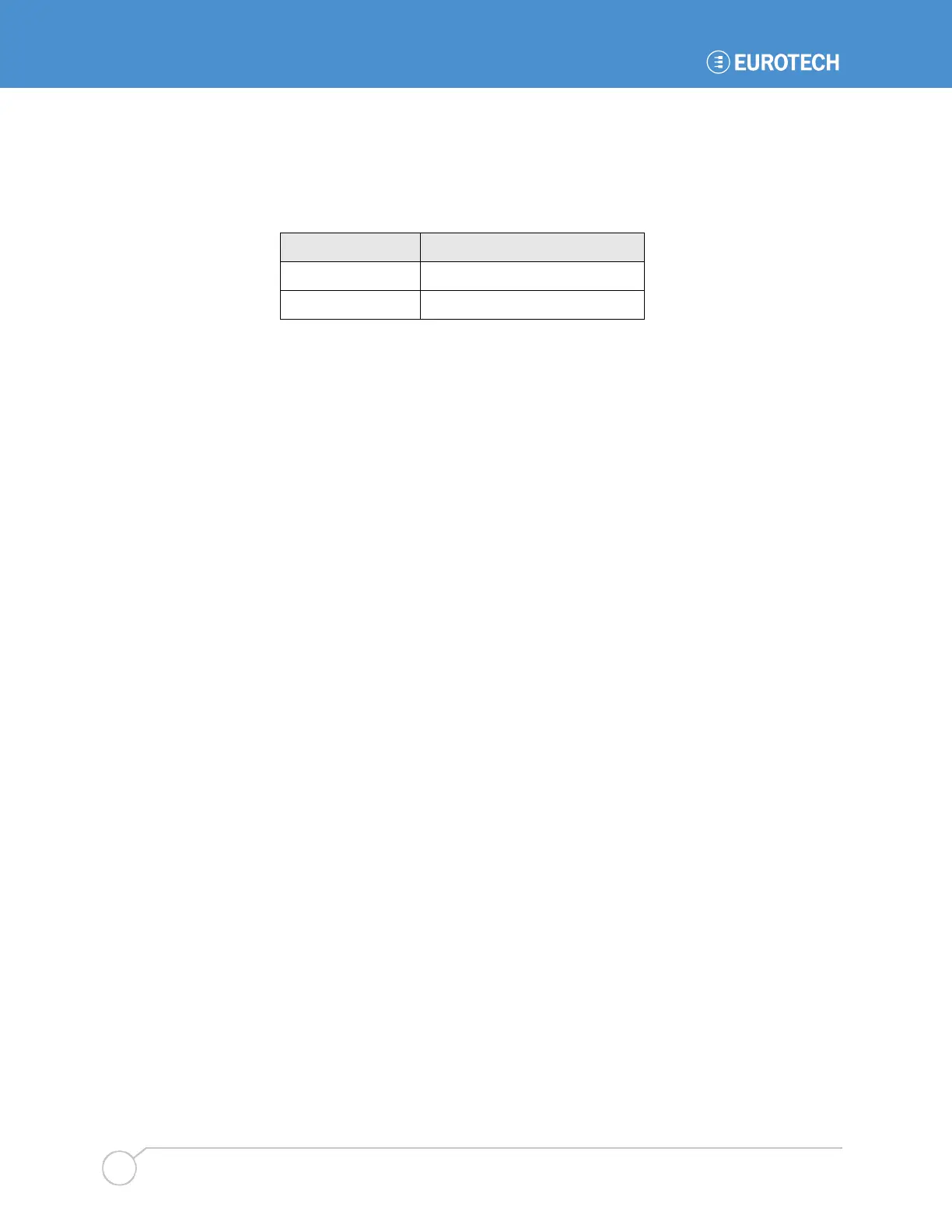
Jumper setting Voltage Selected
1-2 Vddx (3.3 V)
2-3 Vcc (5.0 V)
WARNING! Make sure you have selected the correct voltage before connecting the panel. Flat
panels can be irreparably damaged by incorrect voltages.
3.3 Signal Connectors
The following tables describe the electrical signals available on the connectors of the BitsyXb.
Each section provides relevant details about the connector including part numbers, mating
connectors, signal descriptions, and references to related chapters.
For information about the location of the connectors on the BitsyXb, refer to section 6.1.1.
Legend:
n/c Not connected
GND BitsyXb ground plane
(4.1) Reference section(s) for signals
Signal Types:
I signal is an input to the system
O signal is an output from the system
IO signal may be input or output
P power and ground
A analog signal
OC open collector output