EasyManua.ls Logo

Eurotech BitsyXb - J1: LCD Panel Interface Connector

Eurotech BitsyXb
67 pages
Print Icon
To Next Page IconTo Next Page
To Previous Page IconTo Previous Page
Loading...
Hardware Reference
110118-0001A 15
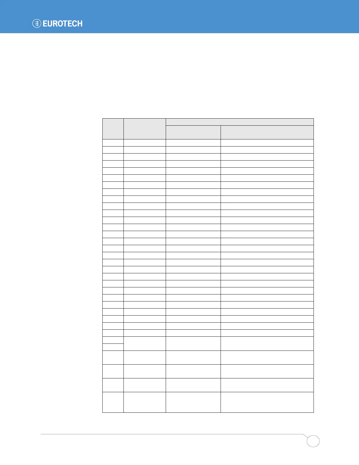
3.3.1 J1: LCD Panel Interface Connector
Board Connector: 2x17 shrouded header, 2mm, Samtec STMM-117-02-G-D
Recommended Board-to-Cable Connector: TCSD series
Recommended Board-to-Board Connector: ESQT series (e.g. ESQT-117-02-F-D-500)
The following table describes the signals on the LCD panel interface connector. Signal names
shown are for TFT active matrix color LCDs at 16 bpp (bit-per-pixel). For other color depths and
LCD technologies, consult the table in section 4.6.4. Signals from the processor are buffered and
EMI filtered before reaching J1. See section 4.6 for further details about displays.
Pin
Signal Name
Color Active TFT Display at 16bpp
Eurotech Signal
Name
Description
1
PNL_VEE
Vee (contrast) (3.3.6, 4.6.7)
2
GND
ground
3
PNL_PIXCLK
Pixel Clock
4
PNL_HSYNC
Horizontal Sync.
5
PNL_VSYNC
Vertical Sync.
6
GND
ground
7
PNL_RED0
Red Bit 0
8
PNL_RED1
Red Bit 1
9
PNL_RED2
Red Bit 2
10
PNL_RED3
Red Bit 3
11
PNL_RED4
Red Bit 4
12
PNL_RED5
Red Bit 5
13
GND
ground
14
PNL_GREEN0
Green Bit 0
15
PNL_GREEN1
Green Bit 1
16
PNL_GREEN2
Green Bit 2
17
PNL_GREEN3
Green Bit 3
18
PNL_GREEN4
Green Bit 4
19
PNL_GREEN5
Green Bit 5
20
GND
ground
21
PNL_BLUE0
Blue Bit 0
22
PNL_BLUE1
Blue Bit 1
23
PNL_BLUE2
Blue Bit 2
24
PNL_BLUE3
Blue Bit 3
25
PNL_BLUE4
Blue Bit 4
26
PNL_BLUE5
Blue Bit 5
27
GND
ground
28
PNL_LBIAS
Data Enable
29
PNL_PWR Vcc (5 V) or 3.3 V ()
30
31
PNL_RL
Horizontal mode select
(set by R193 or R207)
32
PNL_UD
Vertical mode select
(set by R191 or R192)
33
PNL_ENA Panel Enable
34
PD4 VCON
low-voltage adjust for contrast
control of some displays (6.3.2)
(zero to PNL_PWR volts)

Table of Contents

Related product manuals