System Specifications
110118-0001A 61
6.3.7 System Controller
A Xilinx XCR3128 CPLD on the BitsyXb manages /RQOnOff, /PE1, PE2 (section 5.3.2) and
other system control signals. It is programmed at the factory using the JTAG interface (section
3.3.9). The system controller CPLD also manages the PCMCIA and CompactFlash ports.
Specifications are listed separately, below.
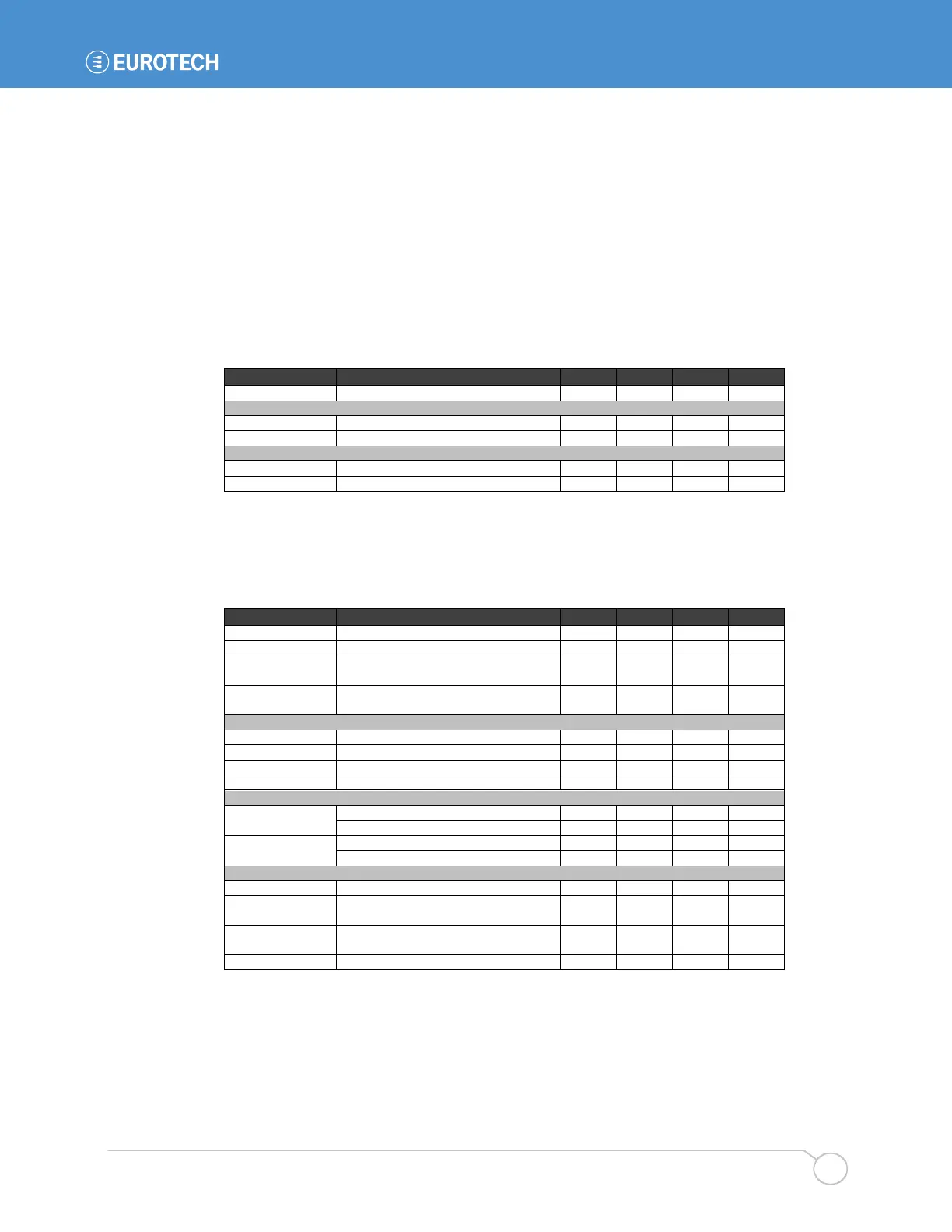
Absolute Maximum Ratings
Input voltage, digital I/O pins ......................... -0.5 to 5.5 V
Output current, continuous,
digital I/O pins .......................................... -100 to 100 mA
Digital Inputs
CompactFlash Port Used as Expansion Bus
The CompactFlash bus can be used as a digital expansion port on the BitsyXb. The following are
specifications for the CF port used as an expansion bus. [tbd]
Rp pcmcia
Card detect (1 & 2) and voltage
sense (VS1 & 2) pull-ups (note)
100
kΩ
Vp pcmcia
Card detect and voltage sense pull-
Vddx Vcc Vcc V
I sink mA
Vil
V
ccb
=3.3 V 0.325 V
ccb
Vih
ccb
t setup1
address setup to command,
first access
2 97 t mem
t setup2
address setup to command,
second access
1 64 t mem
t access nRD/WR duration, first access 3 97 t mem
Notes:
26. Each card inserted in a PCMCIA or CF slot can drain up to 10 mW when the system is in
Sleep mode ( 4 * (Vcc
2
/Rpcmcia) ).
27. The PCMCIA/CF voltage is software-selectable. External implementations of the CF bus
(i.e. on a Personality Board) can hard-wire the voltage to Vddx or to Vcc.
28. The PXA270 MECR register independently sets timings for the attribute, IO and memory
spaces of the CF bus in 32 steps. Values shown assume 206 MHz CPU clock. Min values
are with Fast bit=1, max values are with Fast bit=0.